142. Deformed Bars
Description
This section is from the book "Cyclopedia Of Architecture, Carpentry, And Building", by James C. et al. Also available from Amazon: Cyclopedia Of Architecture, Carpentry And Building.
142. Deformed Bars
There are many forms of reinforcing materials on the market, differing from one another in the manner of forming the irregular projections on their surface. The object of all these special forms of bars is to furnish a bond with the concrete, independent of adhesion. This bond formed between the deformed bar and the concrete, is usually called a mechanical bond. Some of the most common types of bars used are the Ransome, Thacher, Johnson, Diamond, Kahn, and Twisted Lug.
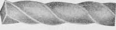
Fig. 13. Ransome Twisted Steel Bar.
The Ransome or twisted bar, shown in Fig. 13, was one of the first steel bars shaped to give a mechanical bond with concrete. This type of bar is a commerical square bar twisted while cold. There are two objects in twisting the bar - first, to give the metal a mechanical bond with the concrete; second, to increase the elastic limit and ultimate strength of the bar. In twisting the bars, usually one complete turn is given the bar in eight or nine diameters of the bar, with the result that the elastic limit of the bar is increased from 40 to 50 per cent, and the ultimate strength is increased from 25 to 35 per cent. These bars can readily be bought already twisted; or, if it is desired, square bars may be bought and twisted on the site of the work.

Fig. 14. Thacher Patent Bar.
The Thacher bar (Fig. 14) was patented by Mr. Edwin Thacher, M. Am. Soc. C. E. These bars are rolled from medium steel, and range in size from 1/4 inch to 2 inches. The cross-sectional area is practically uniform throughout, and all changes in shape of section are made by gradual curves.
The Johnson or Corrugated bar (Fig. 15), with corrugations on all four sides, was invented by Mr. A. L. Johnson, M. Am. Soc. C. E. The corrugations are so placed that the cross-sectional area is the same at all points. The angles of the sides of these corrugations or square shoulders, vary from the axis of the bars not exceeding the angle of friction between the bar and concrete. These bars are usually rolled from high-carbon steel having an elastic limit of 55,000 to 65,000 pounds per square inch and an ultimate strength of about 100,000 pounds per square inch. They are also rolled from any desired quality of steel. In size they range from 1/4 inch to 1 1/4 inches, their sectional area being the same as that of commercial square bars of the same size.

Fig. 15. Johnson Bar.
The Diamond bar (Fig. 16) was devised by Mr. William Mueser. This bar has a uniform cross-section throughout its length, exerts a uniform bonding strength at every section, and every portion is available for tensile strength. In design, this bar consists of a round bar with interlacing longitudinal semicircular ribs, and without any sharp angles. The Diamond bar is one of the newer types of bars.
Fig. 16. Diamond Bar.

Fig. 17. Kahn Trussed Bar.
The Kahn bar (Fig. 17) was invented by Mr. Julius Kahn, Assoc. M. Am. Soc. C. E. This bar is designed with the assumption that the shear members should be rigidly connected to the horizontal members. The bar is rolled with a cross-section as shown in the figure. The thin edges are cut and turned up, and form the shear members. These bars are manufactured in several sizes.

Fig. 18. Cold Twisted Lug Bar.
The Twisted Lug bar (Fig. 18) is similar in form to the Ransome cold-twisted bar, with the addition of lugs or truncated cones placed at regular intervals along the spirals. These bars are rolled with the lugs, and the twisting is done either while the bars are hot or at any time after they are cold. If the bars are twisted while hot, their elastic limit and ultimate strength are not raised; that is, their physical properties are not changed.

KALAMAZOO NATIONAL BANK, KALAMAZOO, MICH.
J. C. Llewellyn, Architect, Chicago, 111.
Reinforced Concrete Floors; Steel Columns Reinforced with Concrete. First Two Stories, Buff Bedford Stone; Upper Stories, Pressed Brick. Built in 1907.
Expanded metal (Fig. 19) is made from plain sheets of steel, slit in regular lines and opened into meshes of any desired size or section of strand. It is commercially designated by giving the gauge of the steel and the amount of displacement between the junctions of the meshes. The most common manufactured sizes are as follows:

Fig. 19. Styles of Expanded Metal.
Standard Sizes of Expanded Metal
Mesh | Gauge | Weight per Sq. Ft. | Sectional Area 1 foot wide |
3-inch | No. 16 | .30 lbs. | .082 sq. in. |
3-inch | No. 10 | .625 lbs. | . 177 sq. in. |
6-inch | No. 4 | .86 lbs. | .243 sq. in. |
Steel wire fabric reinforcement consists of a netting of heavy and light wires, usually with rectangular meshes. The heavy wires carry the load, and the light ones are used to space the heavier ones. There are many forms of wire fabric on the market.
Table XI is condensed from the handbook of the Cambria Steel Company, and gives the standard weights and areas of plain round and square bars as commonly used in reinforced-concrete construetion:
Table XI. Weights And Areas Of Square And Round Bars
(One cubic foot of steel weighs 489.6 pounds)
Thickness or Diameter (Inches) | Weight of Square Bar, 1 Foot Long (Pounds) | Weight of Round Bar, 1 Foot Lono (Pounds) | Area of Square Bar (Sq. In.) | Area of Round Bar (Sq. In.) | ClRCUM OF Round Bar (Inches) |
1/4 | .213 | .167 | .0525 | .0491 | .7854 |
5/16 | .332 | .261 | .0977 | .0767 | .9817 |
3/8 | .478 | .376 | .1406 | .1104 | 1.1781 |
7/16 | .651 | .511 | .1914 | .1503 | 1.3744 |
1/2 | .850 | .668 | .2500 | .1963 | 1.5708 |
5/8 | 1.328 | 1.043 | .3906 | .3068 | 1.9635 |
3/4 | 1.913 | 1.502 | .5625 | .4418 | 2.3562 |
1 | 3.400 | 2.670 | 1.0000 | .7854 | 3.1416 |
1 1/8 | 4.303 | 3.379 | 1.2656 | .9940 | 3.5343 |
1 1/4 | 5.312 | 4.173 | 1.5625 | 1.2272 | 3.9270 |
l 1/2 | 7.650 | 6.008 | 2.2500 | 1.7671 | 4.7124 |
1 3/4 | 10.41 | 8.178 | 3.0625 | 2.4053 | 5.4078 |
2 | 13.60 | 10.68 | 4.0000 | 3.1416 | 6.1823 |
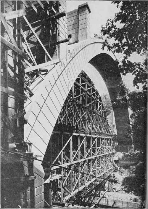
REINFORCED-CONCRETE ARCH RIB, WALNUT LANE BRIDGE, PHILADELPHIA, PA.
Courtesy of Geo. S. Webster, Chief Engineer, Bureau of Surveys, Dept. of Public Work*.
Continue to:
My Books

