Columns. Part 3
Description
This section is from the book "Cyclopedia Of Architecture, Carpentry, And Building", by James C. et al. Also available from Amazon: Cyclopedia Of Architecture, Carpentry And Building.
Columns. Part 3
Plate IX. | ||||
Story heights. | Cols. Nos 1.2.3.4.7.9.11. 12.13.1718.20. 21.22.26 | Cols. Nos 5.6.8.10.14.15. 16,19.23.24.25. 27.28.34 | Cols. Nos 29. 30.31.32. 33.35.36 | |
11-3"x13-8"x12-1"x10-7"x10-7"x10-7"x10-7"x10-7"x10-7"x10-7"x10-7"-variable- | 11th | Web 10"x5816" 4LS. 3 1/2"x3x5/6" | Web 8"x5/16" 4LS. 3 x3 1/2x1/2 | Web 10"x5/16" 4LS. 3 1/2"x3x5/16" |
10th | Area=10.35° Load=36 Tons | Area--16.00° Load=26 Tons | Area=10.85° Load=51Tons | |
9 th | Web 10"x1/2" 4LS. 4"x3"3/8" | Web 10"x3/8" 4LS. 3"x3"x3/8" 2pls 8"x1/2" | Web 10"x1/2" 4LS 4"x4"x1/2" | |
8th | Area = 14.92o Load = 79 Tons | Area = 20.19 Load = 63 Tons | Area = 2000 Load = 108 Tons. | |
7th | Web 10x1/2" 4LS. 4"x3"x3/8" 2pls. 10x3/8" | Web 10"x1/2" 4LS 4"x3"3/8" 2pls 8"x1/2" | Web10"x1/2" 4LS 4"x4"x1/2" 2p[ls 10"x7/16" | |
6th | Area = 22.42o Load = 119 Tons | Area = 23.67o Load = 100 Tons | Area = 28.75o Load = 163 Tons | |
5th | Web 10"x1/2" 4LS. 4"x4"x1/2" 2pls 10x3/8" | Web 10"x1/2" 4LS 4"x4"x1/2" 2pls 10"x1/2" | Web 10"x5/8" 4LS 4"x4"x5/8" 2pls 11"x5/8" | |
4th | Area=27.50° Load=l60Tons | Area=30.00° Load= 136 Tons | Area=38.44° Load=218 Tons | |
3rd | Web 10"x5/8" 4LS. 4"x4"x5/8" 2pls 10"x1/2" | Web 10"x5/8" 4LS. 4"x4"x5/8" 2pls 11"x9/16" | Web10"x3/4" 4LS. 5"x5"x5/8" 2pls 11"x3/4" | |
2nd | Area =34.69° Load= 199Tons | Area=37.07o Load= 173Tons | Area 4744° Load=272Tons | |
1st | Web 12"x3/4" 4LS. 4"x4"5/8" 2pls 10"5/8" | Web 12"x3/4" 4LS. 4"x4"x5/8" 2pls. 11"x3/4" | Web 12"x3/4" 4LS. 5"x5x7/8" 2pls 11"x3/4" | |
Area=39.94o Load=239Tons | Area=43.94o Load=210Tons | Area= 57.46o Load=327Tons | ||
Fig. 107 having been done, the allowable fibre strain, for the least ratio of length and radius of gyration can be taken from the diagram.
If the area as determined by this allowable fibre strain varies materially from that of the assumed section, a new assumption must be made and the process repeated.
Problem. Plot on cross section paper which is divided into spaces 1/10 inch square, a column diagram as described above, and draw curves for each of the formulae given; ordinates to provide for radius of gyration from 0 inches to 8 inches, and of length in feet from 0 feet to 60 feet. The scale to be 2/10 in. = 1 ft., and 2/10 in. = 1 in. radius.
Tables or diagrams are also made of the safe capacity of different column sections for varying lengths, as, for instance, those given for Z-bar columns and for channel and plate columns. Similar data could be prepared for other types of column; but unless the designer were working under one column formula constantly, such tables, in order to be useful, would need to be made applicable to all formulae, and would, therefore, involve considerable time in their preparation.
The column loads should be tabulated with the sections of columns as illustrated by Plate IX, Fig. 107. These loads are the reactions from the different beams framing into them.
Practical Considerations. In general it is the practice to vary the section of column only at every other floor. The reason for this is that the saving in number of pieces to handle and to erect, and in splices, and the gain in time of delivery, more than offset the extra metal added in one story.
In some cases, also, it is advisable to adopt a uniform dimension column so as to avoid changes in length of beam from story to story that would be necessitated by even slight changes in size of column. In special cases many other practical points are likely to arise, which, by affecting rapidity of preparation of drawings, or of shop work, or of erection, may make it advisable to adopt certain forms, or may affect the theoretically economical section. The successful designer is the one who can foresee all these considerations and properly weigh their effect.
Cast-Iron Columns
Where the conditions are such as to require a rigid frame, and consequent stiffness in joints and connections, it is not advisable to use cast-iron columns, because connections to such columns must always be by means of bolts, which are apt to work loose and which never fit the holes perfectly. Furthermore, cast-iron columns are ill adapted to resist lateral deflection. Their use, therefore, should be confined to buildings of moderate height and in which the walls themselves furnish all necessary stiffness.
In order to use the formulas for strength of cast-iron columns, given in Table 10 of Part I, the ends must be turned true. If this is not done not more than one-half their values should be used.
Concrete and Steel Columns
Considerable attention has been given of late to the strength of steel and concrete columns. Some systems have already been proposed, in which columns composed of rods imbedded in concrete are used. Such construction has been used to some extent for chimneys, and in a few buildings. It is also suggested that in certain classes of buildings, notably mills and manufactories, the steel members now quite commonly employed for columns could be encased in a solid and substantial envelope of concrete, and that this casing not only would have the advantage of fireproof protection, but, by the added stiffness afforded the columns, would enable higher fibre strains to be used in the design of the steel members, and would thus result in better and cheaper construction.
Problems
1. Determine by use of the column diagram described in the problem above, the proper section of plate and four-angle column to carry a girder over the top, bringing to the column a load of 100 tons. Unsupported length of column 18 feet. Use Gordon's formula.
2. In the above problem substitute for a plate and angle column a box column composed of channels and side plates, and determine proper section by use of Carnegie formula and American Bridge Company formula.
3. Given a column built into a 16-inch brick pier and loaded with 125 tons. Required the proper section of plate and angle column, assuming column to be stiffened by wall in direction of wall. Length 16 feet. Use Gordon's formula.
4. Given a column loaded as shown by Fig. 114. Determine proper section of plate and angle column, using Gordon's formula.

Fig. 114
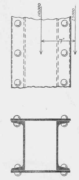
Fig. 115.
5. Given the same column as above, but with the axis of column at right angles to previous position, as shown by Fig. 115. Determine required section of column using channels either latticed or with side plates. Use Gordon's formula.
Continue to:
My Books

