Connecting Joints
Description
This section is from the book "Modern Buildings, Their Planning, Construction And Equipment Vol1", by G. A. T. Middleton. Also available from Amazon: Modern Buildings.
Connecting Joints
Joints For Connecting Struts With Ties
Abutment Plate Joint. - This joint is formed, as shown at A, Fig. 264, by bolting a plate of wood on to the end of the tie against which the foot of the inclined member abuts. The bolts connecting the plate to the tie - which are in single shear - should contain sufficient metal to resist a thrust equal to the tension in the tie.
Plain Abutment Joint
In this joint an abutment is formed for the inclined member by cutting a triangular section out of the tie with one face at right angles to the direction of the inclined member, as seen at B, Fig. 264.
Tenoned Abutment Joint
A joint, similar to that shown at B, but having a tenon formed as shown at C, is called a tenoned abutment joint. In this joint, as in all abutment joints, the distance ab is made equal to about half the depth of the inclined member. The other parts are proportioned as shown.
Bridled Joint
Another satisfactory joint for the connection of ties and struts is the bridle joint, shown at D.
In all these joints the inclined members are prevented from becoming dislodged by means of bolts and straps. Straps passing right round the tie and strut are most suitable, as they do not tend to split the timbers as bolts do.
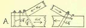
Abutment Pldte Joint.

Abutment Joint.

Tenoned Abutment Joint.
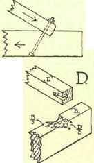
Bridle Jaint.
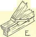
Fig. 264. failure of a Abutment Joint.
At E is shown a type of heel strap which is apt to cause the failure of a timber framework. It should not be used unless the timber is good and thoroughly well seasoned, so that there is no likelihood of a split, such as shown at E.
Fig. 264 also shows how an abutment or bridle joint may fail by the shearing of the end of the tie. To prevent this, the length AB should be calculated by the following formula: -
T = safe resistance to shear along AB, = ABxbxS / factor of safety Where T = tension in tie, ,, b = breadth of beam,
,, S = ultimate resistance of wood to shear per square inch.
Whence AB = 3 T / b x S
Tensile, Compressive And Shearing Strength Of Timber
Description of Timber. | Ultimate Tensile Strength in Direction of Grain. | Ultimate Compressive Strength in Direction of Grain. | Ultimate Shearing Strength | |
With Grain. | Across Grain. | |||
Soft Woods. | Lbs. per sq. In. | Lbs. per sq. In. | Lbs. per sq. In. | Lbs. per sq. In. |
Baltic fir ............... | 4000 | 5000 | 600 | .. |
Cedar ................. | 2900 | 9700 | .. | 1200 |
Pine, American yellow .............. | 2300 | 3000 | 375 | 3600 |
Pine, Oregon ........... | .. | .. | 375 | 2700 |
Pine, Kauric ........... (New Zealand) | 4500 | 5500 | .. | .. |
Pine, Pitch ............ | 4600 | 6000 | .. | .. |
Pine, American red ...... | .. | .. | 210 | 1500 |
Spruce ............... | 4000 | 4600 | 270 | 2250 |
Hard Woods. | ||||
Ash, English .......... | 3700 | 7,000 | .. | .. |
Ash, Canadian ......... | 5500 | 5,500 | .. | .. |
Beech ................ | 4800 | 8,500 | .. | .. |
Blue gum ............. (Australia) | 5400 | 10,000 | .. | .. |
Chestnut ............... | 8000 | .. | 375 | 1200 |
Greenheart ............. | 9000 | 13,000 | .. | .. |
Mahogany, Spanish. | 3600 | 5.500 | . . | .. |
Oak, English, French, Tuscan, Modeno,Sardinian, American White ..... | 7300 | 6,000 | 450 | 3000 |
Ash, Dantzig ........... | 4400 | 6,600 | .. | .. |
Ash, Baltimore .......... | 3800 | 6,000 | .. | .. |
Teak .................. | 3300 | 9,000 | .. | .. |
These figures are the average results of experiments upon fair sized timbers, and a factor of safety of three for dead and six for live loads may be used in preference to Rankine's factors of four and eight, which were based on the results of experiments upon small, carefully selected specimens.
Continue to:
My Books

