Couplings
Description
This section is from the book "Modern Shop Practice", by Howard Monroe Raymond. Also available from Amazon: Modern Shop Practice.
Couplings
Notation
The following notation Is used throughout the chapter on Couplings:
D = Diameter of shaft (Inches). d = Diameter of bolt body (inches), n = Number of bolts. R = Radius of bolt circle (inches). S =Safe shearing fiber stress (lbs. per sq. in.).
Sc =Safe crushing fiber stress (lbs. Per sq. in.). T = Twisting moment (inch-lbs.). t =Thickness of flange (inches). W =Load on bolts (lbs.).
Analysis
Rigid couplings are intended to make the shafts which they connect act as a solid, continuous shaft. In order that the shaft may be worked up to its full strength capacity, the coupling must be as strong in all respects as the shaft, or, in other words, it must transmit the same torsional moment. In the analysis of the forces which come upon these couplings, it is not considered that they are to take any side load, but that they are to act purely as torsional elements. It is doubtless true that in many cases they do have to provide some side strength and stiffness, but this is not their natural function, nor the one upon which their design is based.
Referring to Fig. 51, which is the type most convenient for analysis, we have an example of the simplest form of flange coupling. It consists merely of hubs keyed to the two portions, with flanges driving through shear on a series of bolts arranged concentrically about the shaft. The hubs, keys, and flanges are subject to the same conditions of design as the hubs, keys, and web of a gear or pulley, the key tending to shear and be crushed in the hub and shaft, and the hub tending to be torn or sheared from the flange. The driving bolts, which must be carefully fitted in reamed holes, are subject to a purely shearing stress over their full area at the joint, and at the same time tend to crush the metal in the flange, against which they bear, over their projected area. This latter stress is seldom of importance, the thickness of the flange, for practical reasons, being sufficient to make the crushing stress very low.
Theory
The theory of hubs, keys, and flanges, being like that already given for pulleys and gears, need not be repeated for couplings. The shearing stress on the bolts is the only new point to be studied.
In Fig. 51, for a twisting moment on the shaft of T, the load T at the bolt circle is W = T/R. If the number of bolts be n, equating the external force to the internal strength, we have:
W = T/R = Sπd2 / 4 n. (95)
Although the crushing will seldom be of importance, yet for the sake of completeness its equation is given, thus:
W = T/R = Sodtn. (96)
The internal moment of resistance of the shaft is SD3 /5.1; hence the equation representing full equality of strength between the shaft and the coupling, depending upon the shearing strength of the bolts, is:
SD3 /5.1R = Sπd2 / 4 n. (97)
The theory of the other types of couplings is obscure, except as regards the proportions of the key, which are the same in all cases. The shell of the clamp coupling, Fig. 52, shonld be thick enough to give equal torsional strength with the shaft; but the exact function which the bolts perform is difficult to determine. In general the bolts clamp the coupling tightly on the shaft and provide rigidity, hut the key does the principal amount of the driving. The bolt sizes, in these couplings, are based on judgment and relation to surrounding parts, rather than on theory.
Practical Modification
All couplings must be made with care and nicely fitted, for their tendency, otherwise, is to spring the shafts out of line. In the case of the flange coupling, the two halves may be keyed in place on the shafts, the latter then swung on centers in the lathe, and the joint faced off. Thus the joint will be true to the axis of the shaft; and, when it is clamped in position by the bolts, no springing out of line can take place.
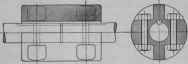
Fig. 52.
A flange F (see Fig. 51) is sometimes made on this form of coupling, in order to guard the bolts. It may be used, also, to take alight belt for driving machinery; but a side load is thereby thrown on the shaft at the joint, which is at the very point where it is desir-able to avoid it.
The simplest form of rigid coupling consists of a plain sleeve slipped over from one shaft to the other, when the second is butted up against the first. This is known as a muff coupling. When once in place, this is a very excellent coupling, as it is perfectly smooth on the outside, and consists of the fewest possible parts, merely a sleeve and a key. It is, however, expensive to fit, difficult, to remove, and requires an extra space of half its length on the shaft over which to be slipped back.
The clamp coupling is a good coupling for moderate-sized shafts, where the flange type of Fig. 51 would be unnecessarily expensive. The clamp coupling, Fig. 52, is simply a muff coupling split in halves, and recessed for bolts. It is cheap and is easily applied and removed, even with a crowded shaft. If bored with a piece of paper in the joint, when it is clamped in position it will pinch the shaft tightly and make a rigid connection. It is desirable to have the bolt.heads protected as much as possible, and this may be accomplished by making the outside diameter large enough so that the bolts will not project. Often an additional shell is provided to encase the coupling completely after it is located.
There are many other special forms of couplings, some of them adjustable. Most of them depend upon a wedging action exerted by taper cones, screws, or keys. Trade catalogues are to be sought for their description.
Continue to:
My Books

