Forming Tools
Description
This section is from the book "Modern Shop Practice", by Howard Monroe Raymond. Also available from Amazon: Modern Shop Practice.
Forming Tools
Forming tools are used when several pieces are to be made of exactly the same shape. They are particularly valuable for giving the desired shape to formed mills and similar tools, and in duplicating a given shape on work produced in the screw machine.
Forming tools are made flat and circular in shape. When used in the lathe for shaping such tools as milling machine cutters, they are generally made flat; for backing off formed milling machine cutters, they are always made flat; for screw machines in duplicating a given shape, they are made both flat and circular.
Flat Forming Tools
The flat forming tool is made as a solid cutter, the tool and shank being in one piece, Fig. 173, or the cutter and shank may be made separate, Fig. 174. When but one forming tool is to be made, the former will be found to be inexpensive; but for making many tools, it will be much cheaper to adopt the latter. Holders. On certain classes of work, it is advisable to use a forming tool on a holder of the kind shown in Fig. 175, which is known as a spring holder. On account of its design, it may spring somewhat when used on heavy cuts, thus reducing the tendency to chatter. It is necessary to make these holders of tool steel, giving them a spring temper at the point marked A. The slot B allows the forming blade D to spring away from the work when under heavy strain. The blades may be planed up in long strips and cut off the required length. The tongue E should fit the slot C, which, with two cap screws through F and G, securely holds the blade in position.

Fig. 173. Flat Forming Tool.
Clearance
In order that a forming tool may cut readily, it is necessary to give the surface marked B, Fig. 174, a sufficient amount of clearance. For tools to be used for shaping milling machine cutters and similar tools, a clearance of from 10 degrees to 15 degrees will be ample; that is, the angle should be from 80 degrees to 75 degrees. But if the tool is to be used for backing off the teeth of formed milling machine cutters, it is necessary to give a clearance of from 18 degrees to 22 degrees. When making a forming tool having the required angle at B, the shape can be produced by tipping the blank to the correct angle and planing or milling with a tool having exactly the desired shape. The tool used may be made of a shape enough different from that desired as to produce the proper shape when the cutter is in a vertical position, and the blank at a given angle from that position, as shown in Fig. 176. Or the tool may be held in the tool post (or in a fixture made for the purpose) of the shaper or planer at the same angle as the blank being cut, Fig. 177, and it will produce a shape corresponding very closely to its own.

Fig. 174. Forming Tool with Separate Shank.

Fig. 175. Spring Forming Tool Holder.
Screw-Machine Forming Tools
In screw-machine and similar work for duplicating given shapes, a forming tool is made like the one shown in Fig. 178. A represents a holder used by the Brown and Sharpe Manufacturing Company for use on their screw machines;
Fig. 170. Tool with Cutter Vortical.

Fig. 177. Tool with Cutter at an Angle.
Fig. 178. Forming Tool for Duplicating Shapes.
B shows the forming tool blank; and the desired shape is cut in the surface marked C.
Circular Forming Tools
These are used very extensively on screw-machine and similar work. They are valuable on account of the ease with which any number of them can be produced, provided a forming tool is used in producing the shape on the face, as shown in Fig. 179.
Milling Cutting Edges
After the blank has been given the proper shape, it may be milled as shown in Fig. 180, in order to provide a cutting edge. If it is desired to produce a shape on the piece being machined, to correspond with the shape of a tool, it is necessary to have the cutting edge radial, Fig. 180. In order to feed the tool into the stock faster than can be done with the form shown, it is given more clearance, Fig. 181. On a tool whose cutting edge is not radial and will not produce a shape corresponding to its own, it is necessary when cutting the edge with the rake shown in Fig. 181, to make the face of the tool slightly different in form from that desired.
Preventing Cracks
After the cutting edge has been milled, the name or number of the tool should be stamped on it, and it is then ready for hardening. When extremely high carbon steel is used, the tools sometimes crack while hardening from the strain incident to their shape. Some tool-makers overcome this tendency by making two extra cuts in the edge, Fig. 182.
Lessening Need For Grinding
Two cutting edges, Fig. 183, are often given a tool, in order that it may not need to be ground so often as when it has but one cutting edge. It is not necessary to stop the screw machine nearly so long to grind both cutting edges, as to stop the machine twice to grind the same edge, on account of the time necessary to rig up the grinder.
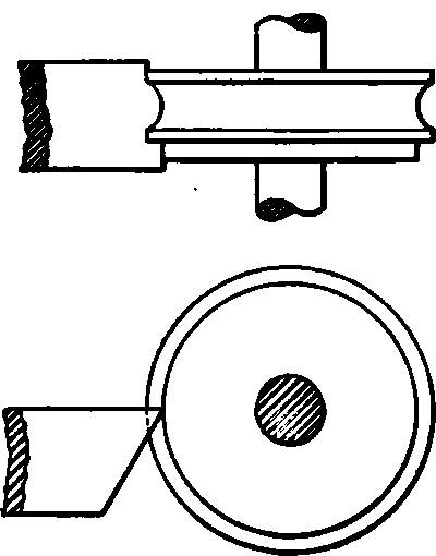
Fig. 179. Straight Forming Tool for Producing Circular Tool.


Fig. 180. Cutter with Radial Cutting Edge.
Fig. 181. Cutter with Offset Cutting Edge.
Hardening
To harden, the tool should be heated to a low red, and plunged into a bath of water or brine from which the chill has been removed; it should be worked around well in the bath. If the temper is not to be drawn after hardening, the tool may be held over the fire after removal from the bath, and heated sufficiently to remove the tendency to crack from internal strains.
Tempering
On account of some weak projection, which, because of its shape, is likely to break when used, it is sometimes necessary to draw the temper. It is not always necessary to draw the temper to a straw color, and as a light straw is the first temper color visible, some other means must be employed. The tool may be placed in a kettle of oil, and with the aid of a thermometer the desired degree of heat may be accurately obtained. The writer recalls a certain forming tool which was too brittle when left as it came from the hardening bath, yet was not hard enough when drawn to even the faintest straw color. After removing from the hardening bath, it was placed in a kettle of boiling water and left about five minutes.

Fig. 182. Cutter with Cuts to Prevent Contraction Cracks.

Fig. 183. Cutter with Double Cutting Edge.

Fig. 184. Tool Holder for Hand Screw Machines.
The heat of the water at 212 degrees reduced the brittleness so that the tool stood up in good shape, yet was not perceptibly softened. The following is an excellent plan: A bath of water having about one inch of oil on top is made ready; the tool, after being heated red hot, is plunged down through the oil into the water. Enough oil adheres to prevent the sudden shock which the steel would receive if plunged directly into cold water. Pack hardening also gives excellent results.
Tool Holders
The form of the holder for the tool depends on the class of work to be done and the machine in which it is to be used. Fig. 184 shows a design commonly used for hand screw-machine work. If the cuts are comparatively light, the side of the tool and holder may be flat, as shown. If, however, heavy cuts are taken which would have a tendency to turn the tool, the latter is often made with a taper projection on one side, Fig. 186, the holder having a corresponding taper hole to receive the projection. This projection should be a good fit in the taper hole, but should not go in far enough to strike the bottom; neither should the side of the tool bear against the side of the holder.
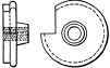
Fig. 185. Cutting Tool for Heavy Cuts.
When used in automatic screw machines, the holder is generally of a different shape from that used for hand screw machines. A very common form is illustrated in Fig. 186. This holder is made in the form of an angle iron, and is fastened to the tool rest by means of the bolt shown. The tool is secured to the upright side of the holder by the bolt, with its head let into the forming tool.
When extra heavy cuts are to be taken with a forming tool, it is sometimes considered advisable to make a holder of the form shownin Fig. 187. The holder is bolted to the tool rest in the same manner as the one represented in Fig. 186. A square thread having a pitch of five or six threads to the inch is cut in the forming tool. The thread should be a right- or left-hand one, depending on which side of the machine the tool is to be located, the thread being such that the tool will tighten by the pressure exerted by the cut. To get an adjustment, the thread in the holder must be of a finer pitch than that in the forming tool, and of the same hand. This tool can, if desired, be employed in the ordinary form of holder shown in Fig. 186, by the use of the bolt shown in Fig. 188.
At times, it is necessary to use two forming tools; these may be arranged to meet the requirements of the individual job. In Fig. 189 are shown two forming tools arranged to cut a desired shape.
High-Speed Steel Forming Tools
At the present time, when high-speed steel is so extensively used in reducing the cost of many machine operations, forming tools are also made from this metal. The high-speed steel tools may be hardened by heating them in specially constructed furnaces, or in a crucible of red-hot lead, and then dipping them in oil, but more satisfactory results are obtained if they are pack hardened by the method already described.

Fig. 188. Adapting Bolt.
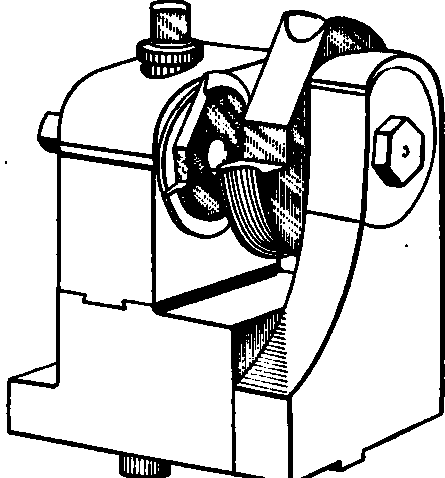
Fig. 189. Arrangement of Two Forming Tools for Special Work.
After pack hardening the tool, it may be necessary to draw the temper somewhat; this will not be needed if the tool is strong and is not to be subjected to severe use. If, however, the tool is weak or has weak projections, it will be found necessary.
Continue to:
My Books

