Keys And Pins
Description
This section is from the book "Modern Shop Practice", by Howard Monroe Raymond. Also available from Amazon: Modern Shop Practice.
Keys And Pins
Notation
The following notation is used throughout the chapter on Keys, Pins, and:
D = Average diameter of rod (inches). Di = Outside diameter of socket (incles). a = Diameter of shaft (Inches). L = Length of key (inches).-P = Driving force (lbs.). P1 = Axial load on rod (lbs.). R = Radius at which P acts (inches). Sc = Safe crushing ober stress (lbs. per bo. in.).
S = Safe shearing flber; stress lbs.;
S =Safe tensile fiber stress (lbs. par; sq., in.). T = Thickness of key (inches). W - Width of key (inches). v = Average width of colter (inches).
w2; = End of slot to end of socket (inches).
Keys And Pins. Analysis
Keys and pins are used to prevent relative rotary motion between machine parts intended to act together as one piece. If we drill completely through a hub and across the shaft, and insert a tightly fitted pin, any rotary motion of the one will be transmitted to the other, provided the pin does not fail by shearing off at the joint between the shaft and the hub. The shearing area is the sum of the cross-sections of the pin at the joint.
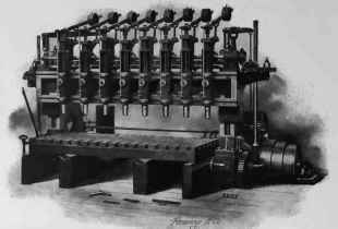
MULTIPLE DRILLING MACHINE. Niles-Bement-Ponnd Co.
We may drill a hole in the joint, the axis of the hole being parallel to the axis of the shaft, and drive in a pin, in which case we introduce a shearing area as before, but the area is now equal to the diameter of the pin multiplied by its length, and the pin is stressed sidewise, instead of across. It is evident in the sidewise case that we may increase the shearing area to anything we please, without changing the diameter of the pin, merely by increasing the length of the pin.
As there are some manufacturing reasons why a round pin placed lengthwise in the joint is not always applicable, we may make the pin a rectangular one, in which case it is called a key.
When pins are driven across the shaft as in the first instance, they are usually made taper. This is because it is easier to ream a taper hole to size than a straight hole, and a taper pin will drive more easily than a straight pin, it not being necessary to match the hole in hub and shaft so exactly in order that the pin may enter. The taper pin will draw the holes into line as it is driven, and can be backed out readily in removal.
Keys of the rectangular form are either straight or tapered, but for different reasons from those just stated for pins. Straight keys have working bearing only at the sides, driving purely by shear, crushing being exerted by the side of the key in both shaft and hub, over the area against the key. The key itself does not prevent end motion along the shaft; and if end motion is not desired, auxiliary means of some sort must be resorted to, as, for example, set screws through the hub jamming hard against the top of the key.
If end motion along the shaft is desired, the key is called a spline, and, while not jammed against the shaft, is yet prevented from changing its relation to the hub by some means such as illustrated in Fig. G5.
Taper keys not only drive through sidewise shearing strength, but prevent endwise motion by the wedging action exerted between the shaft and hnb. These keys drive more like a strut from corner to corner; but this action is incidental rather than intentional, and the proportions of a taper key should be such that it will give its full resisting area in shearing and crushing, the same as a straight key.

Fig. 65.
Theory
Suppose that the pin illustrated in Fig. 66 passes through hub and shaft, and the driving force P acts at the radius R; then the force which is exerted at the surface of the shaft to shear off the pin at the points A and B is 2 PR /d - . If D1 is the average diameter of the pin, its shearing strength is 2π D1 2 S3 /4
Equating the external force to the internal strength, we have :
2PR /d = 2πD1 2 S3 /4;
D1 = √ 4PR / πds3 (103)
In Fig. 67 a rectangular key is sunk half way in hub and shaft according to usual practice. Here the force at the surface of the shaft, calculated the same as before, not only tends to shear off the key along the line AB, but tends to crash both the portion in the shaft and in the bub. The shearing strength along the line AB is LWSS. Equating external force to internal strength, we have:

Fig. 66.

Fig. 67.
2PR/d = LWS.; or, W = 2PR/dLS. (104)
The crashing strength is, of coarse, that doe to-the weaker metal, whether in shaft or hub. Let Sc be this least safe crashing fiber stress. The crushing strength then is - LT/2 S0, and, equating external force to internal strength, we hare:
2PR/d = LT/2 Sc; or, T = 4PR / dLSc (105)
The proportions of the key most be such that the equations as above, both for shearing and for crashing, shall be satisfied.
Continue to:
My Books

