Milling Cutters. Part 5
Description
This section is from the book "Modern Shop Practice", by Howard Monroe Raymond. Also available from Amazon: Modern Shop Practice.
Milling Cutters. Part 5
Keyways
To prevent milling machine cutters from turning on the arbor when cutting, it is necessary, especially when taking heavy cuts, to have keyways cut as shown in Fig, 217 and Table VII.
Fig. 215. Special Form of Inserted.
Courtesy of Morse Twist Drill and Machine Company, New Bedford.
Massachusetts.
Fig. 216. Method of Fastening and Withdrawing Teeth Used by Brown and Sharpe Manufacturing Company.
Fig. 217. Section of Standard Keyway.
Table VII. Dimensions Of Standard Keyways For Cutters
(Letters refer to Fig. 217)
DIAMETER (D) (in). | WlDTh (W) (in). | Depth (d) (in). | Radius (A) (in). | ||
1 | to | 9/16 | 2/32 | 2/14 | .020 |
5/8 | to | 7/8 | 1/2 | 1/16 | .030 |
15/16 | to | 1 1/8 | 3/32 | 5/64 | .035 |
1 3/16 | to | 1 3/4 | 3/16 | 3/12 | .040 |
1 7/16 | to | 1 3/4 | 1/4 | 1/2 | .050 |
1 13/16 | to | 2 | 5/16 | 5/12 | .060 |
2 1/16 | to | 2 1/2 | 3/8 | 2/16 | .060 |
2 9/16 | to | 3 | 7/16 | 3/16 | .060 |
The arbor, of course, must have a similar slot to receive the key. It will be noticed that the dimension d refers to the diameter of the hole in the cutter, and not to the diameter of the cutter. A key-seating machine equipped with the proper tools, furnishes a very satisfactory method of cutting keyways in milling machine cutters, but all shops are not provided with such machines. The form of tool shown in Fig. 218 (A) is extensively used for such purposes on the planer, or shaper, and works well if everything about the machine is in good condition. If, however, there is any looseness in any of the parts, or any backlash in the vertical feed screw, the form Fig. 218 (B) will be found more satisfactory, as it is fed up in the operation of cutting, and the backlash cannot prove a source of annoyance. The writer has found this form of tool satisfactory on all interior cutting on the shaper and planer. It is necessary to clamp the tool head so that it cannot rise on the return motion of the planer.

Fig. 218. Forms of Keyway Cutters for Planer or Shaper.
In shops where many cutters having holes of the some size are made, a saving of time will be effected, if there is a draw-broaching machine, by broaching the keyway. A number of cutters having the same size of arbor hole can be broached in a fraction of the time necessary to cut them on the planer or shaper with the key-slotting tool shown; when, however, but one cutter is to have the keyway cut, the planer method may prove to be quicker.
As all stock is not perfectly homogeneous, tools of the description shown will not always cut an absolutely straight slot. For most purposes, the amount of variation need not be considered; but when an absolutely straight cut is necessary, the form of tool shown in Fig. 218 (c),is used. The portion marked e is made .001 or.002inch smaller than the hole through which it is to pass. The cutter is set in a slot which passes through the tool as shown, and is fed into the work by means of the pointed feed screw.
Fig. 219. Special Formed Cutter Courtesy of Union Twist Drill Company, Athol, Massachussetts.
Formed Cutters
As used by the Brown and Sharpe Manufacturing Company, the term formed cutter applies to cutters with teeth so relieved that they can be sharpened by grinding without changing their form. The term can be applied, however, to any cutter which cuts a form, regardless of the manner in which the teeth may be relieved. Fig. 219 represents a formed cutter. Formed cutters are used in many shops where work of irregular shape is milled in large quantities, as in sewing machine, gun, bicycle, and automobile shops.
If many formed mills are to be made, it is advisable to procure or make a machine specially designed for relieving-backing off-the teeth. As such machines are heavy and rigid, large cutters may be relieved and a smooth cut obtained, which is not possible with a light machine.
Backing-Off Lathe Attachments
Although this style of cutter can be made to better advantage in a shop equipped with machinery designed especially for this class of work, an ordinary engine lathe can be converted into a backing-off lathe for relieving or backing off the cutters. There are several commercial devices for the work: one comparatively inexpensive fixture is known as the "Balzar" backing-off attachment, Fig. 220; another arrangement consists simply of an eccentric arbor operated by a hand lever; or, a stud may be screwed into the faceplate of a lathe and the cutter placed on this stud in a position that allows the teeth to be given the necessary amount of clearance.
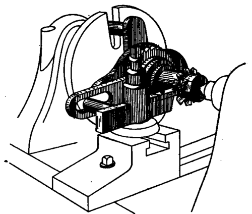
Fig. 220. Balsar Backing-Off Attachment.
. When backing off the teeth of cutters whose faces do not exceed one inch in width, the Balzar backing-off fixture can be used to advantage. This device is held between the centers of a lathe in the ordinary manner, the backing off being such that the cutter can be ground without alteration of shape. The tool is so constructed that it is only necessary to place the cutter upon the arbor in the ordinary way. Place the arbor on the lathe centers as shown, start the lathe, and feed the forming tool in by the cross-feed screw in order to take the desired cut, in the same manner as in plain turning. The ratchet connected with the arbor and actuated by the pawl, contains ordinarily 36 teeth, and the stroke can be set to back off a cutter with 9,12,18, or 36 teeth.
Continue to:
My Books

