Plug Gages
Description
This section is from the book "Modern Shop Practice", by Howard Monroe Raymond. Also available from Amazon: Modern Shop Practice.
Plug Gages
Plug gages are those used to measure the size of a hole.
To make the plug gage shown in Fig. 413, stock should be selected enough larger than finish size to allow for turning off the decarbonized surface. After roughing out, the handle B should be turned to size and knurled, the portion C should be turned to size and finished, and the spot in the center of the handle should be milled. The size of the gage and any distinguishing mark or name of the article to be gaged may be stamped at B, as shown, or, as is the custom in many shops, it may be done at C. After stamping, the gage end A may be turned to a size .010 or .015 inch larger than finish, to allow for grinding. Plug gages should be heated very carefully for hardening, as the lower the heat, the more compact will be the grain; and a piece of steel whose grain is fine and compact will wear better than one whose grain is coarse. If the gage is one requiring great accuracy, it may be left .0025 or .003 inch above size and allowed to season, provided this precaution is deemed necessary; if not, the gage may be ground to a size .001 inch larger than finish, after which it must be lapped to finish size.
Casehardening Machine-Steel Gages
When plug gages are made of machine steel, they should be casehardened in the following manner: They may be packed as for pack hardening, that is, in charred leather. They should run in the furnace for seven or eight hours after they are red hot. The box should then be taken from the furnace and allowed to cool, after which the gage, enclosed in a piece of tube, may be heated in an ordinary fire. When it reaches a low red heat, it should be plunged into a bath of raw linseed oil. It will not be necessary to draw the temper, and the danger of alteration as it ages is done away with.
The reason for not hardening when the gage has run the required length of time in the furnace, is that the effect of the second heat is to refine the steel, making the grain more compact, like properly hardened tool steel, thus increasing its wearing qualities.
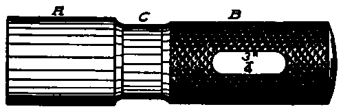
Fig. 413. Typical Plug Gage.
Grinding
When grinding a gage of this description, it is advisable to use a grinding machine having a supply of water running on the work to keep it cool, but if this form of grinder is not available, the gage should not be heated any more than is necessary. It should be measured while cool, as steel always expands from the action of heat, and if ground to size when heated, would be too small after cooling.
If possible, a form of grinder having two dead centers should be used - that is, one in which neither center revolves. This is mentioned on account of the tendency in some shops where there is no universal grinder, and an engine lathe is to be used as a grinder, to select the poorest lathe in the shop for the purpose. Lathes that have been in use for some time are very likely to have become worn, so that accurate work is impossible; this is especially true of the head spindle, which will duplicate its own inaccuracy on the piece being ground.

Fig. 414. Good Form of Lap for Cylindrical Surfaces.
If obliged to do the work on a machine of this description, it is advisable to leave a trifle more stock for lapping than if a suitable grinder is used. A coarse wheel free from glaze should be employed to grind within .001 of finish size, after which a finer wheel may be substituted to grind to lapping size.
Lapping
A very simple method of making a lap for use on a cylindrical surface is shown in Fig. 414; this consists of a piece of cast iron having a hole bored a trifle larger than the size of the gage to be ground. It is split as shown, and closed by means of the screw A.
If there is much gage or other work requiring lapping, it is advisable to make a lap as shown in Fig. 415. The holder A has a hole bored to receive the laps, which are made in the form of rings, split in three places, which fit the holder. One cut is carried through one wall; while the other two, commencing at the inside, terminate a little distance from the outside surface. The laps may be held in place by means of the pointed screw shown at B.
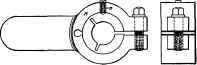
Fig. 415. Lap for Gages.
The lapping should be done with flour emery mixed with oil. This operation has the effect of heating the gage to a degree that would make it unsafe to caliper, and on this account it is necessary to have a dish of water handy in which to cool the gage before measuring it. This water should not be cold, or incorrect measurements will result; it should be as nearly as possible the average temperature of the room in which it is to be used, about 70 degrees.
Grinding Off End
After the tool has been lapped to the required size, it may be placed in a chuck on the grinding machine and the end ground off to remove any portion that is slightly smaller than the rest of the gage, as the lapping is likely to grind the extreme end slightly tapering. In order to save time when grinding the end, the gage may be made as shown in Fig. 416. The sectional view shows the end cupped in, leaving a wall 1/16 inch to 1/8 inch thick, according to the size of the gage, the larger sizes having the thicker walls; the cupping should be about 1/16inch deep and the corner left slightly rounded, as shown.
Another method is to cut a groove with a round-nosed cutting-off tool, leaving a disc on the end, Fig. 417. If the gage has its end shaped as in Fig. 416, the projecting portion, A A, is ground away until the end of the gage is straight across. In case the gage is made as shown in Fig. 417, the disc A is broken off and the end ground as described.
Continue to:
My Books

