342. The Universal Milling Machine
Description
This section is from the book "An Elementary Outline Of Mechanical Processes", by G. W. Danforth. Also available from Amazon: An elementary outline of mechanical processes.
342. The Universal Milling Machine
The machine in Fig. 196 is known as a plain milling machine because its table cannot turn on the saddle. The machine in Fig. 197 is a universal milling machine, as its saddle is made in two parts, divided horizontally at H and so adjusted that the upper part may revolve on a vertical spindle on the lower part, allowing the table to be turned to a considerable angle from its position as shown in the plain machine. The junction of the two parts of the saddle is marked by a graduated circle so that the angle through which the table is moved can be readily measured.
The parts of the machine (similarly named to those of the plain machine) are as follows:
S. Spindle.
C. Driving cone.
F. Back gear.
B. Elevating screw.
H. Saddle.
TT. Work table.

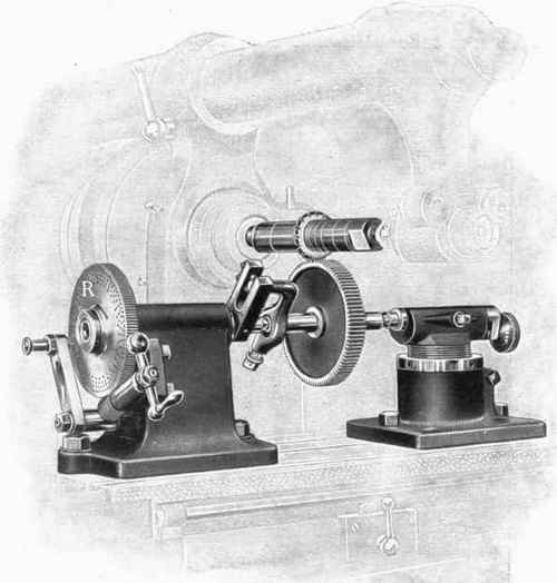
Fig. 197. - Universal Milling Machine.
A. Arbor.
N. Arbor support.
GG. Over-arm.
MM. Over-arm brace.
D. Brace clamp.
KK. Knee.
EE. Trip dogs. L. Feed shaft. J. Reverse lever. W. Dividing head. X. Foot stock.
The dividing head and foot stock correspond to the head and tail stocks of a lathe. The dividing head is used in cutting gear wheels, sides of prisms, and similar work which must be divided into an exact number of parts around its periphery, as shown in
The Hendey Machine Co. Torrington, Conn.
Fig. 198. - Example of Milling-Machine Cutting.
Fig. 198. Divisions are regulated by the dividing wheel R. When work suspended on the centers of the dividing head and the foot stock must be given a motion of revolution as part of the operation of milling it, the gear wheels Q (Fig. 197) are connected to the feeding mechanism of the machine. For cutting spiral grooves and coarse threads, the work is revolved on these centers and at the same time is given a motion of translation by the movement of the table.
Continue to:
My Books

