Making An Electric Bell
Description
This section is from the book "American Library Edition Of Workshop Receipts", by Ernest Spon. Also available from Amazon: American Library Edition Of Workshop Receipts.
Making An Electric Bell
The following description applies to 3 sizes - viz. for a 2 - in. bell, hereafter called No. 1; 2f - in., or No. 2; 4 - in., or No. 3, which sizes are sufficient for most amateurs' purposes, and, if properly made, a No. 3 Leclanche cell will ring the largest 2 through over 100 yd. No. 24 (B. W. G.) wire.
The Backboard And Cover
This may be of any hard wood, by preference teak, oak, or mahogany, and if polished, so much the better; the size required will be -
No.l, | 5 1/2 | in. | long, | 3. | in. | wide, | i | in. | thick. |
No. a, | 7 | in. | " | 3. | in. | " | . | in. | " |
No. 3, | 8 1/2 | in. | »» | 6 | in. | ♦» | . | in. | " |
The cover must be deep enough to cover all the work, and reach to within, about 1/4 in. of the top and sides of back, and allow 3/8 in. to 3/4 in. between the edge of bell and cover; the making of this had better be deferred until the bell is nearly complete.
The Electro - Magnet
This should be of good round iron, and bent into a horse - shoe shape (Fig. 41). The part a b must be quite straight, and not damaged by the forging; the bend should be as flat as possible, so as to make the magnet as short as may be (to save space).
Fig. 41.
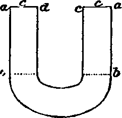
When made, the magnet is put into a clear fire, and when red hot, taken out and laid in the ashes to slowly cool; care must be taken not to burn it. Lastly, 2 small holes are drilled in the centre of the ends at c, about 1/16 in. deep; drive a piece of brass wire tightly into the holes, and allow the wire to project sufficiently to allow a piece of thin paper between the iron and the table when the iron is standing upon it; this is to prevent the armature adhering to the magnet from residuary magnetism, which always exists more or less. The measurements are -
No. 1 | size iron | 1/4 in., | dtoe | . | in., | a to 6 | 1 1/4 | in. |
No. a | »• | " | 4 | in., | ,, | 1 3/2 | in. | |
No. 3 | »» | 7 /16 in., | " | . | in., | »» | 1 1/2 | in. |
The Bobbins Or Coils
These are made by bending thin sheet copper round the part a 6 of the magnet; the edges at a (Fig. 42) must not quite meet. The thickness of this copper must be such that 4 pieces just equal in thickness the edge of a new threepenny - piece (this is rather an original gauge, but then all can get at the thickness this way). The hole in the brass end b must be just large enough to push on firmly over the copper when on the iron; they must then be set true, and soldered on. The brass for the ends may be about as thick as a sixpence; a 1/16 - in. hole must be drilled at c, close to the copper. The other measurements are as follows: -
Fig. 42.

No. 1, diameter 3/8 in., length over all 1 1/5 in. No. 2, „ . in., „ l 1/4 in.
No. 3, „ l in., „ 1 3/8 in.
The brass ends should be neatly turned true, and lacquered.
How To Fill The Bobbins With Wire
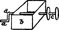
For this purpose, No. 28 wire should be used, which is better if varnished or paraffined. The bobbins should be neatly covered with paper over the copper tube and inside of ends, to prevent any possibility of the wire touching the bobbin itself; the bobbin is best filled by chucking it on a mandrel in the lathe, or a primitive winding apparatus may be made by boring a hole through the sides of a small box, fit a wire crank and wooden axle to this, and push the bobbin on the projecting end - thus (Fig. 43): a, crank; b, box;c, bobbin; d, axle. The box may be loaded to keep it steady; on any account do not attempt to wind the wire on by hand - the bobbin must revolve. Leave about 1 1/2 in. of wire projecting outside the hole d, in end of bobbin, and wind the wire on carefully and quite evenly, the number of layers being respectively 6,8, and 10; the last layer must finish at the same end as the first began, and is best fastened off by a silk or thread binding, leaving about a 3 - in. piece projecting. Both bobbins must be wound in the same direction, turning the crank from you, and commencing at the end nearest the box.
The bobbins must now be firmly pushed on the part a b of the magnet, and the two pieces of wire projecting through the holes c soldered together.
Fig. 43.
How To Put The Bell Together
First screw on the bell. This should be supported underneath by a piece of 1/4 - in. iron tube, long enough to keep the edge of the bell 3/8 to 5/8 in. above the backboard. Cut off the hammer - rod, so that when the head is on it will come nearly as low as the bell screw, and in a line with it. Make a hole in the backboard, and drive the armature post in tightly - it must be driven in so far that when the magnet is laid upon the backboard, the centre of the magnet iron and the armature are the same height. Place the magnet so that when the armature is pressed against it, the hammer - head all but touches the bell; screw it into its place by a wooden bridge across the screw passing between the bobbins. By afterwards easing this screw, any little adjustment can be made. The armature spring should tend to throw the hammerhead about 5/8in. from the bell. The contact - post should be so placed that when the armature touches the magnet, there is a slight space between the platinum point on the screw and the platinum on the spring. In putting in the posts, a piece of copper wire must be driven in with them to attach the wire to.
One post can be moved round a little either way to alter the tension of the spring; the screw in the other post can be turned in or out, to just allow the proper break to take place. By screwing it in and out, the ear will soon judge where the bell rings best. (Volk.)
Examples
It will doubtless be of considerable assistance to many amateurs to have a few examples illustrated and explained.
(1) Trembling Bell
- Make an electromagnet, either out of 3/8 - in. iron bent round, or a piece of iron bent at a right angle, into which 2 cores can be screwed as at a, Fig. 44. On each of these cores wind 2 oz. 26 silk - covered wire; you may wind directly on to the iron, or make a bobbin; if you wind on to the iron, first with paraffin paper. The arms on a spring containing the hammer at the other end. The spring is continued apart from the armature to a platinum - pointed screw c; this enables you to adjust the armsture to a very great nicety. Lines show the connection of wires from binding - screws to electro - magnet. Of course, these wires go underneath the board. The bell d is suspended on a brass or iron post, with a thnmb - nu' on the top, screwing down on to the bell; 2 good Leclanche cells would wor' this bell well. (2) A (Fig. 45) is the bell. Th consists of an electro - magnet a, with a vibrating armature b; c is a brass spring tipped with platinum, which keeps the circuit closed so long as the bell is not ringing.
Continue to:
My Books

