Bollards
Description
This section is from the book "Notes On Construction In Mild Steel", by Henry Fidler. Also available from Amazon: Notes On Construction In Mild Steel.
Bollards
Among the necessary items of equipment on a wharf, jetty, or dockside, for the handling of ships or vessels of all sizes, not the least important are the bollards for the attachment of mooring hawsers.

Fig. 366. Scale 3/16 inch = 1 foot.
These may be occasionally of stone, and are frequently of timber in those cases where the outer piles of a timber jetty of pier are carried up above the level of the deck. In modern dock work, where the class of craft which comes alongside includes some of the heaviest ships afloat, it is customary to make the bollards of cast iron, and latterly in first-class work they have been constructed of cast steel.

Fig. 367. Scale⅜ inch = 1 foot.
It is obvious that where very large vessels are concerned it is necessary for safety in handling that the detail of attachment of the shore end of the hawser should be above suspicion as far as it is possible to make it so, as the failure of a bollard at a critical moment may have serious results. The consideration of the stresses which may arise from the pull of a steel wire or hempen hawser will lead to the conclusion that the case is not quite so simple as may appear at first sight.
The direction of the pull of the hawser in a horizontal plane may be at any angle within a semicircle on the wharf side, or even practically all round the circle in those cases where a lead can be taken off a bollard in almost any direction, while there will frequently exist a vertical component of pull tending to pull the bollard out of the ground in cases of attachment to a high-sided ship.
Again, there may exist a powerful element of torsion whenever the hawser, as is frequently the case, is taken with several turns round the bollard, and the pull is at one side or edge instead of being led to the centre.
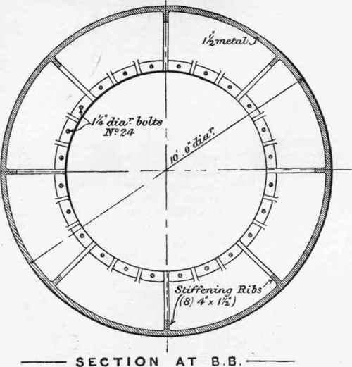
Fig. 368. Scale ⅜ inch = 1 foot.
In all the varying degrees of angle at which the pull may occur, the ultimate strength of the hawser itself may, however, be taken as the measure of the strength of the bollard. When the hawser parts, the duty of the bollard is at an end, while it is probable that the strength of the shore attachment, as usually designed, is at least equal to that customary on board ship. The consideration of this latter detail belongs, however, to the domain of naval architecture.

Figs. 369,370. Scale 1½ inch = 1 foot.

Fig. 371. Scale 1 inch = 1 foot.
The calculation of bollard strength on these lines presents no special difficulty, using the moment of inertia of the section under consideration, and assuming the maximum height or lever arm at which the pull is likely to take place, while the torque can be calculated in the usual manner. The strength of the foundation in which the bollard is fixed must necessarily be governed by circumstances, and is not always capable of precise calculation. The bollard may be fixed in a solid wall, and there may be cases in which the stability of the whole wall must be considered, while if fixed near the edge, the resistance to bursting of the masonry or concrete in front of the bollard must not be lost sight of, and where this resistance is insufficient or doubtful, it has to be supplemented by ties to the back of the wall. In those cases where a bollard is fixed in an isolated block of concrete, which itself is buried in soil, possibly made ground, the resistance to overturning of the concrete block is supplemented to some extent by the resistance of soil of varying degrees of softness or compressibility, and in such cases the total resistance offered may not be easily calculable. It is certainly possible, and has occurred in practice, that the bollard with its foundation may be pulled out of perpendicular, aided by a vertical component of stress, before the transverse resistance of the bollard itself had been reached. This part of the subject belongs, however, to the theory of the strength of foundations generally, or rather to that branch of it which deals with resistances in soils other than vertical.

Fig. 372. Scale 3/16 inch = 1 foot.

Fig. 373. Scale 1 inch = 1 foot.

Fig. 374. Scale 1 inch = 1 foot.

Fig. 375. Scale 1 inch = 1 foot.

Fig. 376. Scale 1 inch = 1 foot.
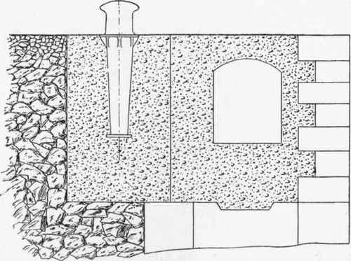
Fig. 377. Scale 3/16 inch = 1 foot.

Fig. 378. Scale ¾ inch = 1 foot.

Fig. 379. Scale ¾ inch = 1 foot.
The position of bollards with relation to the edge of coping or wharf line is often determined by varying considerations. In some cases it is deemed desirable to keep the bollards back and leave a working space alongside the edge of jetty or dock, but in these cases the space in question will be encumbered by the hawsers themselves. Where this is deemed objectionable, as in those cases where a railway line, or crane road of wide gauge, or both combined, are required alongside the wharf or dock, then the bollard is frequently placed as close to the edge as is practicable, and in many cases is placed flush with the face of the wharf wall.

Fig. 380. Scale 3/16 inch = 1 foot.
These varying conditions give rise to a variety of detail governed by the various methods employed of tieing back the bollard to a sufficiently good foundation to meet all the conditions of stress.
In Fig. 377 we have the case of a simple form of bollard embedded in a concrete block at the back of a quay wall, there being a subway in the top of the wall to contain hydraulic or electric mains, water pipes, etc. The upper portion of this bollard is shown in part elevation and section in Fig. 378, and in sectional plan on the line HH in Fig. 379, which shows the shape of that portion of the bollard to which the hawser is attached, the lower portion, embedded in the concrete foundation, being made square to prevent turning round under torsional stresses. It will be observed that the lower portion of the square is cast with a projecting lip offering resistance to a vertical component in the pull. The mushroom-shaped head at the top of the bollard prevents slipping upwards of the hawser.
A special form of cast-iron bollard to meet special conditions is shown in Fig. 380. In this case it is required to place a bollard as near the coping line of a commercial wharf as possible, in order to leave behind it an unencumbered space for crane and wharf roads. The outer rail of the crane road is placed on the coping to facilitate the design of the travelling crane to be employed and reduce overhang. The space required for this rail (not shown in the figure), and the dimensions of the crane leg and its gear, require the bollard to be set back a little from the coping line as shown, while we have almost immediately under the bollard a subway for the purposes above described.

Fig. 381. Scale 3/16 inch = 1 foot.
This combination of conditions gives rise to the form shown in Fig. 380. The under surface of the casting is shaped as shown to suit the outline of the subway, while the necessary tieing back is secured by the 3-inch diameter bolts which are carried to the back of the wharf wall, which is widened out in way of the bollards to provide sufficient mass.
Fig. 381 is an elevation of the rear of the wall showing the attachment of the tie-rods, and Fig. 382 is a plan of the general arrangement. Fig. 383 is a longitudinal section of the front portion of the bollard, and Fig. 384 is a section through MM, Fig. 383.
Figs. 385, 386, and 387 are details of the rear portion of the bollard, showing the attachments of the 3-inch diameter ties. These ties pass through a cast-iron washer similar to that shown in Fig. 375, resting on a stone bed plate embedded in the concrete of the wall.

Fig. 382. Scale 3/16 inch = 1 foot.
The front portion of the bollard is held down by a pair of 2½ -inch diameter rods, embedded in the wall as shown.
Another form of bollard suitable for heavy vessels, and adopted in its details for attachment to a jetty of composite construction having a timber superstructure, is shown in Fig. 346, while the attachments of a bollard of special construction to suit the details of riveted steel girderwork in a jetty of another type are shown in Figs. 358, 359, 362, 363.
In combination with a system of bollards, the complete equipment of a modern jetty or wharf will also include fairleads and capstans, the latter being driven by steam, compressed air, hydraulic, or electric power, in accordance with the type of power available.
The relative position of bollards, fairleads, and capstans should be carefully studied and planned out in order that the lead of the hawser may be as free as possible and not exposed to chafing.
Where very heavy vessels have to be manipulated, the anchorage of the fairleads should be of a substantial character, and it is desirable that the foundation should offer ample resistance to drawing out or overturning. If a fairlead be planted, for example, on a coping stone, damage by loosening the stone may result, unless the latter be very firmly secured. An independent foundation, consisting of a concrete block of sufficient dimensions, is often found a preferable course.
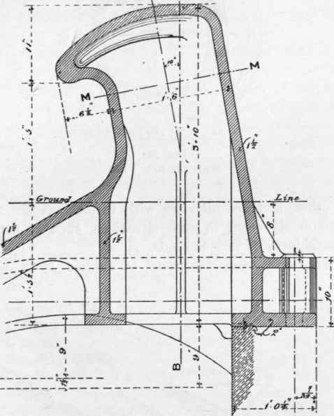
Fig. 383. Scale ¾ inch = 1 foot.
The general arrangements of bollards, fairleads, and capstans at the entrances to docks and basins will generally require a careful study in detail, not only to secure the best and most advantageous positions for the handling of incoming and outgoing vessels, but also that they may occupy positions in proper relation to each other, and not interfere with various machinery details which commonly occur in such situations, such as penstock or caisson machinery of various kinds.
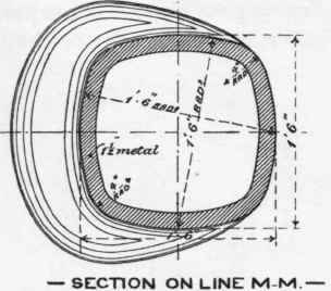
Fig. 384. Scale¾ inch = 1 foot.
Continue to:
My Books

