Caissons
Description
This section is from the book "Notes On Construction In Mild Steel", by Henry Fidler. Also available from Amazon: Notes On Construction In Mild Steel.
Caissons
The term "caisson" is applied to a variety of structures fulfilling varied functions and serving widely different purposes. Thus we have the term applied to that form of structure designed to close dock entrances, and forming virtually a movable dam. Reference to this form of construction will be made later on. Or we may find it applied to those appliances by the aid of which the foundations of important structures, such as large bridges, are sunk to great depths, often under conditions of great difficulty and risk. Or again, as before mentioned, the term is applied to a class of structure by means of which breakwaters constructed in deep water are either commenced or, as it sometimes happens, are brought to a conclusion by the formation of the head of the breakwater inside, or by means of, a caisson.

Figs. 385, 386, 387. Scale ¾ inch = 1 foot.
In this chapter practical examples, recently carried out, will be given of two classes of caissons, viz. those employed under special circumstances for the commencement of an important breakwater, and those employed for the closing of dock entrances.
A recently completed breakwater,1 constructed of concrete blocks, laid by what is known as the sloping system of blockwork was commenced subsequently to the deposit of an extensive rubble mound, designed so as to bring the foundation level of the block-work from the sea bottom upwards to about 36 feet below low water, by a steel caisson designed by the author, and of the form shown in longitudinal section in Fig. 388. This caisson may be described as a rectangular box with sloping ends, and having the following principal dimensions : -
Length moulded on bottom | 101' 2½" |
Length moulded on top of fixed part ... | 73' 10½" |
Length moulded on portable bulwarks ... | 72' 10½" |
Breadth moulded ... | 33' 0" |
Depth moulded of fixed part ...... | 37' 6" |
Height of portable bulwarks ...... | 11' 0" |
Length of well moulded......... | 60' 0" |
Angle of sloping ends ......... | 70° |
The caisson was of a uniform moulded breadth, as above, of 33 feet, this being the normal width of the blockwork construction, while the slope of the end portions, 70 degrees, was the angle at which the sloping blocks were laid, both ends of the caisson being sloped to the same angle, the intention being to sink the caisson at or near the centre of the breakwater and commence work in both directions simultaneously, the blockwork in one-half of the breakwater sloping in the opposite direction to that in the other half.
1 For a description of this work, the student is referred to the article on "Dockyards" by the author of these notes in the Supplement to the Encyclopaedia Britannica.

Fig. 388. Scale 1 inch = 16 feet.
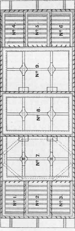
Fig. 389. Scale 1 inch = 16 feet.
The caisson was divided lengthwise into five chambers, the two end chambers being watertight compartments with a combined total displacement calculated to ensure the caisson, with all ballast and temporary fittings and gear on board, floating with a maximum draught of 32 feet, thus having a clearance of 4 feet under the bottom, over the finished and prepared surface of the rubble mound before mentioned.
The three central compartments formed an open well, with no bottom, and having a total moulded length of 60 feet, each compartment being 20 feet in moulded length, with a breadth moulded of 33 feet.
The intermediate bulkheads and the side plating of the central well were watertight, the bottom being open, but framed with strong plate girders longitudinally and transversely, as shown in the figures.
The end watertight compartments were each subdivided by fore-and-aft bulkheads into three separate watertight compartments, the entire structure being thus divided into nine compartments, as shown in plan in Fig. 389 (which is a section on A, B, Fig. 388) and numbered 1 to 9. The object of this subdivision will be explained later on. Fig. 390 is a cross-section of the caisson taken partly through the end compartments, and partly through the central well.
The caisson was constructed of mild steel of the usual quality.
The frames were of 8" X 3½" X 3½" X ⅜" Zeds, spaced 2 feet apart, centres, the stringers in the end watertight compartments, Nos. 1 to 6, consisting of a web plate 24" X ⅜", cut for the frames, and brought up to and riveted to the skin plating in the usual way, with an angle steel 3" X 3" X ⅜" for each flange.
The stringers to compartments 7, 8, and 9 consisted of a web plate 24" X ⅜", with flange angles 3" X 3" X f", attached to the bulkheads and frames by means of brackets and bolted connections in such a way as to render them removable in the central well compartments prior to the deposit of concrete, this course being adopted in order that the deposited concrete in the central well might have as few dividing planes of weakness as possible. The stringers in compartments Nos. 1, 2, 3, 4, 5, and 6 were not removable, being riveted to the skin plating.
The skin plating was of mild steel plates, arranged in and out, nine strakes in height, the three lowermost being ½ inch thick, the three next 7/16 inch, and the three uppermost § inch thick. The landings of skin plating and bulkheads were double riveted throughout, with double riveted butt straps, and double riveted overlap butts to bulkheads.
The riveting, principally ¾ inch diameter, was spaced 4 to 4½ diameters in watertight work, 7 to 8 diameters in non-watertight work, and with special spacings elsewhere.
The "floors" or floor girders stiffening the bottom ½-inch plating of end watertight compartments were of 18" X ⅜" web, with one 3" X 3" X ⅜" angle to each flange.
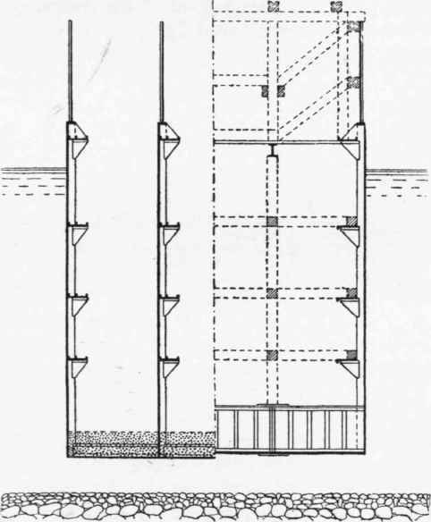
Fig. 390. Scale 1 inch = 16 feet.
The plate girders at the bottom of the central well compartments Nos. 7, 8, and 9 were longitudinal and intercostal, as shown, and consisted of webs 60" x ⅜", with top and bottom flanges of two 6" X 6" X ½ angles, double riveted, with one plate 12½" x ½", the webs being stiffened at 2 feet intervals with 3" X 3" X ⅜" angles, the junctions of longitudinal and intercostal girder being further stiffened by top and bottom sketch plates as shown. The purpose of these stiff bottom girders was to resist, in combination with concrete, upward water pressure at certain stages of the filling of the central well with concrete, and pumping out of the several compartments.
Continue to:
My Books

