Girderwork As Applied To Bridge Construction
Description
This section is from the book "Notes On Construction In Mild Steel", by Henry Fidler. Also available from Amazon: Notes On Construction In Mild Steel.
Girderwork As Applied To Bridge Construction
It is obviously impossible in a collection of notes such as the present to deal even in the most elementary manner with the details of bridge construction in steel. The subject is one of immense extent, and the details of even one such structure of the first class and of very large span would suffice to fill a volume of itself.
The example here chosen is selected merely as typical of the application of plate girderwork to a comparatively small structure of short spans, but as the work includes some other useful details of various kinds, it will be further discussed.
The structure in question forms a viaduct connecting certain outlying jetties and wharves with the mainland.
The roadway is therefore designed to carry a mixed traffic of foot passengers, railway lines, and ordinary road vehicles, together with certain provision made for pipe-work, such as hydraulic mains, etc. This combination required an arrangement of roadbed or bridge-floor adapted to meet the requirements of the conditions above described.
Fig. 33 gives an elevation of one span of the viaduct, which is formed of a pair of heavy plate girders supported on cast-iron cylinders placed 60 feet apart longitudinally, and 25 feet 9 inches centre to centre transversely, as shown in Fig. 34, which is a cross-section of the viaduct at the centre of one of the spans, the clear width of roadway between main girders being 24 feet.
The cast-iron cylinders were constructed in lengths of 6 feet in height as a rule, certain special or make-up lengths being supplied to reach the prescribed finished level at the girder-beds in accordance with the slightly varying depths to which the cylinders were sunk, determined by the nature of the strata reached, and by the amount of settlement of the cylinder under the prescribed test-load.
These lengths of cylinder were each cast in one complete ring without vertical joint.
This method of construction can be easily carried out up to about 10 feet or thereabouts in diameter. For larger diameters it is usual to cast them in segments with vertical joints, a system which offers some advantages for shipment abroad.
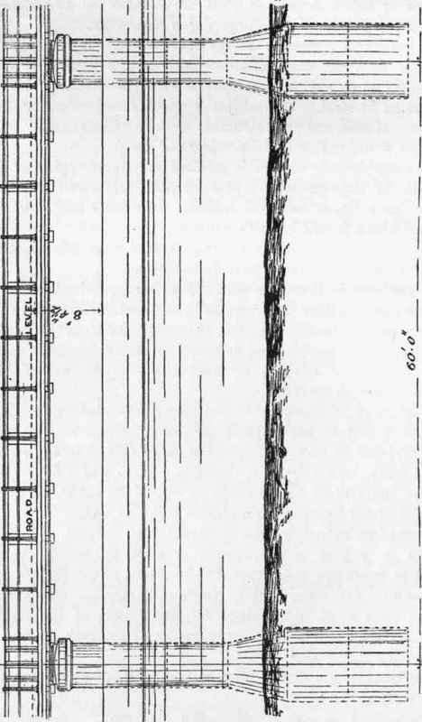
Fig. 33. Scale 1 inch = 12 feet.
The bottom lengths are 7 feet 6 inches in diameter. Above these is the taper length shown in Figs. 33 and 34, leading to a reduction in diameter for the uppermost lengths which maintained a uniform diameter of 4 feet 6 inches up to the level of the capping which forms the capital of the column. The lowermost of the bottom lengths is furnished with a cutting edge, as shown in Fig. 35, for convenience in penetrating the strata through which the cylinder has to pass, being sunk by the combined processes of undercutting at the cutting edge, and forcing down by dead weight applied at the top, the interior of the cylinder being kept dry by the use of the compressed air system, an air-lock being used for passage into and out of the cylinder.
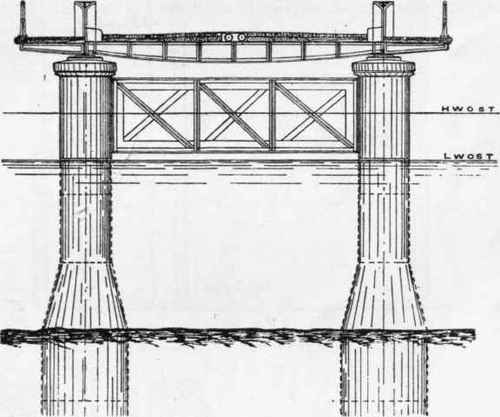
Fig. 34. Scale 1 inch = 12 feet.
The enlarged diameter at the bottom of the cylinder affords facilities for the necessary excavation.

Fig. 35. Scale 1½ inch = 1 foot.
The lengths of cylinders were stiffened by internal vertical ribs as shown in Fig. 36, which also shows the nature of the horizontal joint and bolted connection between the bottom lengths, the section of the joint being further shown in detail in Fig. 37.

Fig. 36. Scale \ inch = 1 foot.
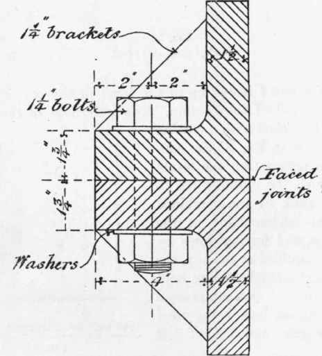
Fig. 37. Scale 3 inches = 1 foot.
It will be observed that between every bolt a triangular stiffening bracket is cast connecting the flange with the metal skin of the cylinder.
The flanges are machined for their entire width, while all the bolt-holes are drilled, ensuring sound work and the precise duplication of the joints.
The water- tightness of these joints is secured by the use of canvas and red lead, or by an indiarubber ring about ¼ inch diameter placed between the machined faces and squeezed out by the bolting up of the joint.
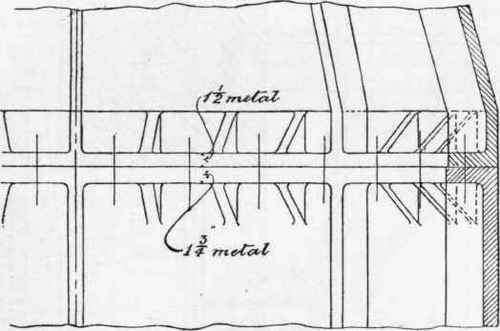
Fig. 38. Scale ¾ inch = 1 foot.
It has occasionally happened that either from the existence of initial cooling stresses in the casting, or from certain inequalities of stress arising from the forcing down of the cylinder through hard and difficult strata, the bottom length of cylinders such as those now under consideration have cracked more or less seriously during the process of sinking, and this has led some designers to adopt a riveted form of construction for the lowermost length.
The horizontal joint between the lower lengths and the taper or conical length next above them is shown in Fig. 38.
The joints of the upper lengths of reduced diameter are similar to that shown in Fig. 37.
The upper portion of the cylinder at the level of the capping and girder bedstones is shown partly in elevation and partly in section in Fig. 39. The moulded cap or capital is cast separately from the cylinder length, is of ¾-inch metal, cast in a convenient number of segments, and is bolted to the top length of cylinder in the manner shown in Fig. 41, which shows a detailed section of the moulding, while Fig. 40 shows the internal elevation at a joint of the segments.
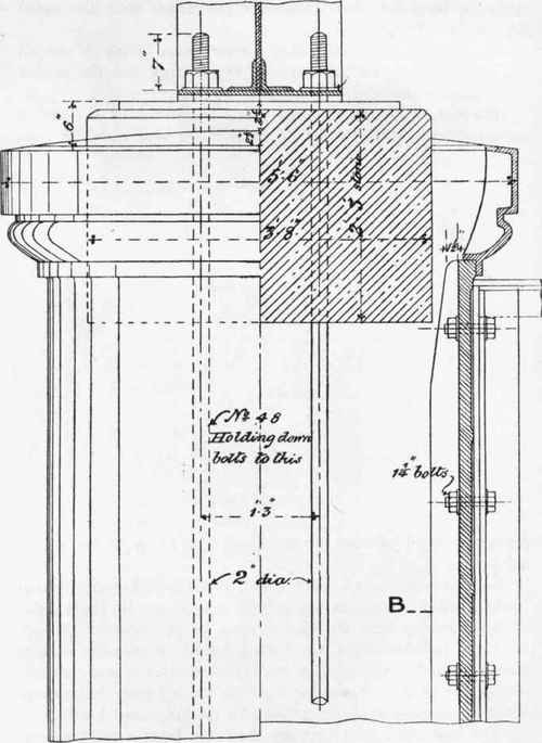
Fig. 39. Scale ¾ inch = 1 foot.
Within the capping, a hard stone girder-bed of the dimensions shown in Fig. 39 is inserted, resting upon the concrete with which the cylinders are filled, to receive the ends of the 60-feet main girders.
Continue to:
My Books

