Lanterns, Skylights, And Ventilators. Part 2
Description
This section is from the book "Notes On Construction In Mild Steel", by Henry Fidler. Also available from Amazon: Notes On Construction In Mild Steel.
Lanterns, Skylights, And Ventilators. Part 2
A fair idea of the degree of Watertightness obtainable by such an arrangement as that shown can be obtained, by the construction of a model of two or more rows of the blades in zinc full size. Water sprinkled or poured upon the blades will collect in drops at the lower edge, and if a drop be subjected to a powerful current of air, as, for example, from the nozzle of a pair of bellows, it can be ascertained whether it is possible to blow the drop over the top of the next blade below, the experiment forming a rough approximation to the condition of rainfall, combined with a horizontal or inclined current of air in a gale of wind blowing across the lantern.

Fig. 277. Scale 1½ inch = 1 foot.

Fig. 278. Scale 1½ inch = 1 foot.
Louvre blades which warp or sag after erection present a very-unsatisfactory appearance, and, in consequence the distance apart of louvre standards should be regulated so as to give sufficient stiffness to the blade, or the cross-section of the blade must be so designed as to give the requisite stiffness for the span to be adopted. In the cases above described the blades were capable of spanning a distance up to about 7 to 8 feet, but beyond this distance an intermediate support became desirable.
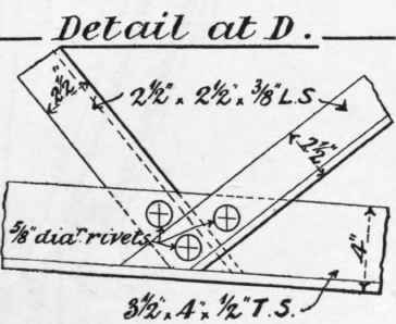
Fig. 279. Scale 1½ inch = 1 foot.

Fig. 280. Scale ⅜ inch = 1 foot.
Roof lanterns and ventilators usually occupy exposed positions, and all their fastenings and connections should be such as will afford due security under these conditions.
Roofs of flat pitch are frequently adopted in cases where, for architectural reasons, it is 'desirable that the roof construction should be concealed behind parapet walls or other architectural feature. This condition gives rise to a class of roof truss which approximates more to the form of a lattice girder, with sloped upper flange, than to the ordinary form of roof principal usually classed under that term.

Fig. 281. Scale ⅜ inch = 1 foot.
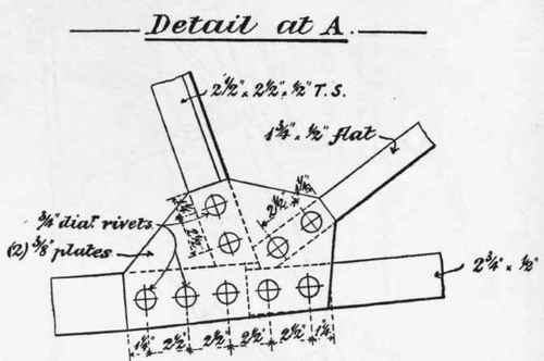
Fig. 282. Scale \\ inch = 1 foot.

Fig. 283. Scale 1½ inch = 1 foot.
An example of this type is shown in Fig. 270, which shows a portion of the truss nearest the wall end, the section of the wall itself with the parapet being shown, and the architectural features of the cornice and string courses being broken off for convenience.

Scale 1½ inch = 1 foot.
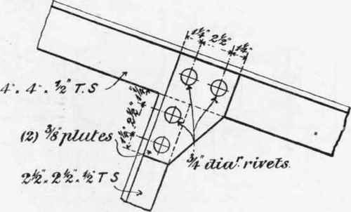
Fig. 285. Scale 1½ inch = 1 foot.
The roof is of flat pitch, the covering being of zinc on boarding laid with drips and falls as shown, and the slope of the upper member of the truss arranged to suit. The lower or tension member is curved or given a large camber for appearance sake. In Fig. 271 the centre portion of the truss is given, showing the lantern and skylight, which is glazed with ¼-inch rough rolled plate in wood sash bars, or with one of the numerous forms of patent glazing. Ventilation is secured, as in previous examples, by galvanized wrought iron or mild steel louvres secured to cast-iron standards, with an additional ventilator at the ridge of the skylight framed in timber and covered with zinc.
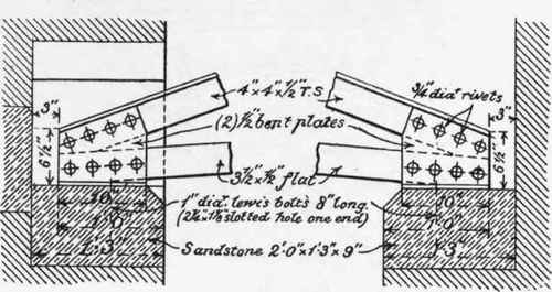
Fig. 286. Scale ¾ inch = 1 foot.
Fig. 287. Scale ¾ inch = 1 foot.
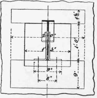
Fig. 288. Scale ¾ inch = 1 foot.

Fig. 289. Scale ¾ inch = 1 foot.
The end of the truss opposite the wall rests upon a riveted steel plate girder carrying a heavy water tank, and the detail of attachment to the girder, together with the assemblage at this point of the truss, girder, tank, gutter, and roof-covering detail, is shown in Fig. 272, with a sectional elevation of the connection of truss to girder in Fig. 273.

Fig. 290. Scale 1 inch = 1 foot.
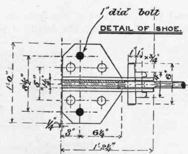
Fig. 291. Scale 1 inch = 1 foot.
The details of the tank, together with the weathertight connection between the tank and the gutter, are referred to in Chapter III (Upon Certain Applications Of Riveted Girderwork, With Some Remarks Upon Rivets And Rivet-Holes)., and shown in the figures therein described.
The detail of the wall end of the truss is shown in Fig. 274, with section of the wall gutter, while a sectional elevation of the end of the truss, showing its seating on the wall, on the line AA, Fig. 274, is shown in Fig. 275.

Fig. 292. Scale ⅜ inch = 1 foot.
The upper and lower members of the truss are T steels, and the intermediate bracing of angles. The details of connections at the points A, B, C, and D, Figs. 270 and 271, are shown in Figs. 276, 277, 278, and 279 respectively.
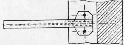
Fig. 293. Scale ⅜ inch = 1 foot.
It will be observed that no joint is shown in the upper member at A, or in the lower member; this course being only permissible where the span of the truss, or considerations of transport or erection, will allow of the truss being sent away and erected in one piece.

Fig. 294. Scale 1½ inch = 1 foot.
Details of a roof principal of ordinary pitch, with a covering of zinc on boarding, and resting upon walls at both ends, are given in Figs. 280 to 289 inclusive.

Fig. 295. Scale 1½ inch = 1 foot.
Continue to:
My Books

