On The Practical Design Of Columns And Struts. Part 15
Description
This section is from the book "Notes On Construction In Mild Steel", by Henry Fidler. Also available from Amazon: Notes On Construction In Mild Steel.
On The Practical Design Of Columns And Struts. Part 15
The general arrangement of the building is such that any-overturning moment due to horizontal wind pressure acting at the top of the column is divided between several rows of columns, the whole being enclosed between masonry walls of a substantial character. Consequently the amount of holding-down power required to resist such a moment was not excessive, and the group of eight foundation bolts shown in detail in Fig. 221 provided a sufficient resistance. The arrangement of these bolts is shown in plan in Fig. 235, and it will be observed that their washers, in this case, consist of simple steel flats, 1 inch thick, arranged as shown.
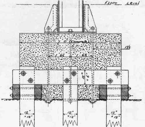
Fig. 233 (Scale ⅜ inch = 1 foot).

Fig. 231 (Scale ⅜ inch = 1 foot).
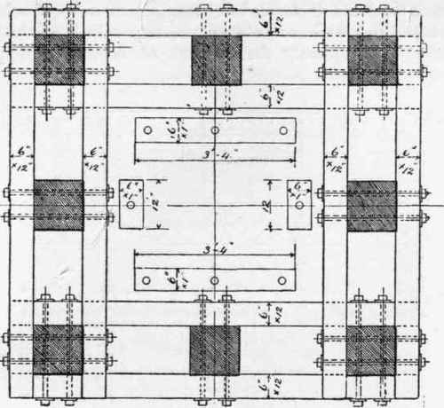
Fig. 235 (Scale | inch a 1 foot).

Fig. 236 (Scale 1 inch - 24 feet).

Fig. 237. Scale 1 inch = 16 feet.
Under other conditions of construction, however, the question of lateral stability of the whole structure against wind pressure may be of greater importance, and require special provision to ensure sufficient resistance to an overturning moment.

Fig. 238. Scale ½ inch = 1 foot.
Especially may this be the case where the building is lofty and the enclosing walls composed of timber or corrugated sheet-iron, or both combined, having no great weight in themselves, and therefore requiring a sufficiency of stability in the column anchorages.

Fig. 239. Scale ½ inch = 1 foot.
An instance of this class is illustrated in Fig. 236, showing a cross-section of a building designed to carry 70-ton travellers at a height of rail level of 41 feet 4 inches above ground, the elevation of one bay of the building being shown in Fig. 237.
In this case the columns of riveted wrought iron rest upon massive concrete foundations, carried down to a reliable stratum underlying soft alluvial deposit.
The section of this column, which is 49 feet in total height, is of the type shown in Fig. 167, and the details of the base and anchorages are shown in Figs. 238, 239, 240, 241,242, and 243. It will be seen that the holding-down bolts resisting overturning moments transversely to the building are 3 inches in diameter, of mild steel, with circular cast-iron washers, while sufficient stability in the longitudinal direction of the building is afforded by bolts 2¼ inches in diameter.

Fig. 240. Scale ½ inch = 1 foot.
The attention of the student is directed to the means by which the heavy anchorage bolts take hold upon the riveted column base.
The detail of the cap of the column and the seating provided for the traveller girders is given in Fig. 244, and the section of the traveller girders showing elm timber sleeper forming continuous bearer to rail in Fig. 245, the timber being notched to the stepping up of the plates in top flange, the traveller girder in this case being of uniform depth, and not fish-bellied.

Fig. 241. Scale ½ inch = 1 foot.

Fig. 242. Scale½ inch = 1 foot.
In such a case as the foregoing, the fixing of heavy anchorage bolts during erection requires careful attention to ensure that the bolts themselves do not sink beyond their true level when concrete is being deposited around them, as in such an event the screwed portion of the bolts may be found insufficient in length to pass through the whole depth of the nut, a contingency which points to the desirability of an ample margin of length in the bolt and its screwed portion, the labour of cutting off excess length in such conditions being preferable to any loss of strength in the hold on the nut.
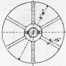
Fig. 243. Scale \ inch = 1 foot.

Fig. 244. Scale ½ inch = 1 foot.

Fig. 245. Scale ½ inch = 1 foot.
The accuracy of position of all anchorage bolts in plan should be secured by the use of templets.
Continue to:
My Books

