Rolled Joists
Description
This section is from the book "Notes On Construction In Mild Steel", by Henry Fidler. Also available from Amazon: Notes On Construction In Mild Steel.
Rolled Joists
This well-known, most useful, and deservedly popular section is shown in Fig. 13.
The web is most commonly rolled with parallel sides, the flanges being tapered, and connected to the web with roundings in the internal corners. The proportion of web thickness to flange thickness, the amount of taper on the latter, the radii of the roundings, have been, as in other sections, variable with different makers. These proportions exert some influence on the precise values of the moments of inertia and resistance, and the manufacturers of this section frequently give in their trade catalogues the mechanical elements and exact proportions of the sections rolled by them. This course is commendable in preference to the compilation of tables of strengths in which the data of the calculations are absent.
In the British standard section the thickness of web and flanges, the taper of the latter, and the radii of the connecting curves, are all standardized, and the mechanical elements of the standard section will be found in the publication previously referred to.
The depths of this section as usually found in the market range from 3 inches to 24 inches, and the width of flange from 1¼ inch to 8 inches.
This width of flange has recently been exceeded in continental rolling mills, and the section thus produced offers considerable advantages in column design owing to the increase of the least radius of gyration, and in the arrangement of details in connections, where the additional space afforded is often very convenient. Notwithstanding the width of flange the section can be very cleanly rolled, right out to the edge of the flange, and straight and true in its length.
The proportions of depth and width require careful consideration when selection is being made of a section suitable for the purpose in view. The economy of this section as regards riveting, and the facility with which, aided by the table of strengths obligingly furnished by the manufacturer, the selection of a section for strength can be made, undoubtedly contribute to the favour in which the rolled joist is held. It is questionable, however, as a matter of taste, how far the indiscriminate use of the section, especially in the largest sizes, contributes to the artistic appearance, if it may be so called, of well-designed ironwork, and it must be confessed that economy of both cost in manufacture and painstaking in design are frequently attained at the expense of appearances. It is to be feared, however, that any regard for appearances in structural steelwork, if it implies any increase in cost, real or imaginary, will in these competitive days be regarded by many as an economic heresy.
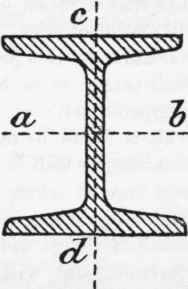
Fig. 13.
No universally recognized standard of proportion of the flanges and web of rolled joists had, up to a recent period, been arrived at by manufacturers. Published lists of sections show considerable variation in the proportion of web thickness to flange width, of web thickness to height of joist, of mean thickness of flange as compared with width, or with height of joist. The thickness of web is found to range between seven and twelve hundredths of the flange width in joists of 3½ inches width of flange and upwards, and may be taken to average about eight hundredths. In joists under 3½ inches in flange width the web will average about one-tenth of flange width. The mean thickness of flange is equally variable, and will be found to range between five and nine hundredths of the height of joist in joists above 6 inches high. In shallower joists the mean flange thickness will range from eight to twelve hundredths.
The maximum moment of inertia of the cross-section will increase in value per unit of area as the web becomes thinner, but the student need not be reminded that the moment of inertia is not the only standard of the ultimate actual strength of the joist. Apart from the practical requirements of the rolling mill the web must be thick enough not only to withstand the usual web stresses, but also to resist the effects of corrosion, and to assist the top flange to resist the buckling tendency under compression which is found in practice to limit the strength of the joist when not supported laterally, the compression flange under these conditions usually failing by lateral flexure before the full tensile resistance of the metal in the lower flange has been attained.
Within the usual limits of variation of web thickness as rolled by different manufacturers, the maximum value of the moment of inertia compared with the total sectional area or weight per foot run will be attained when the flange thickness is from nine to ten hundredths of the height of the girder, but the economic efficiency is practically equally as great between the limits of six and twelve hundredths, and the lower value of flange thickness is the one more usually found in joists above 6 inches in height.
The following table is based upon an assumed web thickness of 0.08 (width of flange) in all joists above 3½ inches wide, and 010 (width of flange) in joists under that width. The values of the moments of inertia (taken about the axis a - b) are given for varying proportions of flange thickness, and these will be found to cover the variations usually found in practice. The radii of gyration (for use in column and strut design) are given about the axes a - b and c - d respectively.
Table No. 27. The Principal Mechanical Elements Of Rolled Joists
(See Fig. 13.)
Flange thickness Depth of joist. | Section of joist. | Area in square inches. | Weight in lbs. per foot run. | Moment of inertia about the axis a - b. Fig. 13. | Radii of gyration. | Distance of axis a - b from farthest edge of section. | |||
Axis a - b. | Axis c - d. | ||||||||
0.05 | 20" | X | 7½" | 25.8 | 88 | 1646.4 | 7.92 | 1.60 | 10.00 |
0.06 | " " | 28.56 | 97 | 1864.8 | 8.08 | 1.72 | " | ||
0.05 | 19¾" | X | 7¼" | 24.59 | 84 | 1530.0 | 7.85 | 1.60 | 9.87 |
0.06 | »! »» | 27.25 | 93 | 17358 | 7.99 | 1.66 | " | ||
0.05 | 18" | X | 7" | 21.67 | 74 | 1120.2 | 7.20 | 1.50 | 9.00 |
0.06 | »> »» | 23.99 | 81 | 1268.8 | 7.27 | 1.60 | " | ||
0.05 | 17¾" | X | 6¾" | 20.57 | 70 | 1029.2 | 7.09 | 1.49 | 8.87 |
0.06 | " " | 22.80 | 78 | 1165.7 | 7.11 | 1.55 | " | ||
0.05 | 16" | X | 6" | 16.51 | 56 | 674.3 | 6.38 | 1.22 | 8.00 |
0.06 | " " | 18.27 | 62 | 763.8 | 6.40 | 1.25 | " | ||
005. | 16" | X | 5" | 13.76 | 46 | 561.9 | 6.42 | 1.10 | 8.00 |
0.06 | " " | 15.23 | 52 | 636.5 | 6.46 | 114 | " | ||
0.05 | 15¾" | X | 6⅛" | 16.55 | 56 | 656.4 | 6.30 | 1.35 | 7.87 |
0.06 | " " | 18.35 | 62 | 743.7 | 6.37 | 1.41 | " | ||
0.05 | 15" | X | 6" | 15.48 | 53 | 555.6 | 5.98 | 1.30 | 7.50 |
0.07 | " " | 18.79 | 64 | 700.0 | 6.10 | 1.35 | " | ||
0.05 | 15" | X | 5 ½" | 14.19 | 48 | 5093. | 5.97 | 1.21 | 7.50 |
0.07 | " " | 17.22 | 58 | 641.7 | 6.10 | 1.26 | " | ||
0.05 | 15" | X | 5" | 12.90 | 44 | 463.0 | 5.98 | 1.00 | 7.50 |
0.06 | " »» | 14.28 | 49 | 524.5 | 6.05 | 1.04 | " | ||
0.05 | 14" | X | 6" | 14.45 | 49 | 451.8 | 5.62 | 1.30 | 7.00 |
0.06 | ' " | 15.99 | 54 | 511.7 | 5.65 | 1.35 | " | ||
0.05 | 14" | X | 5½" | 13.24 | 45 | 414.1 | 5.60 | 1.21 | 7.00 |
0.06 | " " | 14.66 | 50 | 469.0 | 5.64 | 1.26 | " | ||
0.05 | 13" | X | 5" | 11.18 | 38 | 301.4 | 5.18 | 1.10 | 6.50 |
0.06 | " " | 12.37 | 42 | 341.4 | 5.24 | 114 | " | ||
0.06 | 12" | X | 6½" | 14.85 | 51 | 349.1 | 4.84 | 1.49 | 6.00 |
0.07 | " " | 16.29 | 55 | 388.3 | 4.88 | 1.54 | " | ||
0.06 | 12" | X | 6" | 13.71 | 47 | 322.2 | 4.85 | 1.35 | 6.00 |
0.08 | " " | 16.36 | 56 | 392.8 | 4.92 | 1.40 | " | ||
Flange thickness Depth of joist. | Section of joist. | Area in square inches. | Weight in Ibs. per foot run. | Moment of inertia about the axis a - b. Fig. 13. | Radii of gyration. | Distance of axis a - b from farthest edge of section. | |||||||
Axis a - b. | Axis c - d. | ||||||||||||
0.06 | 12" | X | 5½" | 12.56 | 43 | 295.4 | 4.86 | 1.26 | 6.00 | ||||
0.08 | " " | 14.99 | 51 | 359.9. | 4.90 | 1.33 | " | ||||||
0.05 | 12" | X | 5" | 10.32 | 35 | 237.1 | 4.80 | 1.10 | 6.00 | ||||
0.06 | " " | 11.42 | 38½ | 268.5 | 4.85 | 1.15 | " | ||||||
0.07 | 10½" | X | 5" | 10.96 | 37 | 200.1 | 4.27 | 1.18 | 5.25 | ||||
0.08 | " " | 11.93 | 41 | 219.3 | 4.29 | 1.21 | " | ||||||
0.05 | 10¼" | X | 4¾" | 8.37 | 28½ 3l| 38| | 140.3 | 4.08 | 1.04 | 5.125 | ||||
0.06 | " " | 9.25 | 159.0 | 4.17 | 1.09 | " | |||||||
0.06 | 10" | X | 6" | 11.42 | 186.5 | 4.04 | 1.38 | 5.00 | |||||
0.08 | " " | 13.63 | 46.5 | 227.3 | 4.08 | 1.46 | " | ||||||
0.05 | 10" | X | 5" | 8.60 | 29 | 137.2 | 3.99 | 1.10 | 5.00 | ||||
0.08 | " " | 11.36 | 38½ | 189.4 | 4.08 | 1.21 | " | ||||||
0.06 | 10" | X | 4½" | 8.57 | 29 | 139.8 | 4.03 | 1.03 | 5.00 | ||||
0.08 | " " | 10.22 | 35 | 170.5 | 4.08 | 1.09 | " | ||||||
0.06 | 9½" | X | 4.1" | 8.12 | 27½ | 119.6 | 3.88 | 1.03 | 4.75 | ||||
0.08 | " " | 9.70 | 33 | 145.8 | 3.90 | 1.09 | " | ||||||
0.06 | 9¼" | X | 4" | 7.04 | 24 | 98.4 | 3.74 | 0.91 | 4.625 | ||||
0.08 | " " | 8.40 | 281 441 52½ | 119.9 | 3.78 | 0.96 | " | ||||||
0.07 | 9" | X | 7" | 13.15 | 176.4 | 3.66 | 1.65 | 4.50 | |||||
0.09 | " " | 15..47 | 209.5 | 3.68 | 1.73 | " | |||||||
0.06 | 9" | X | 5½" | 9.40 | 32 | 124.6 | 3.64 | 1.26 | 4.50 | ||||
0.08 | " " | 11.24 | 38 | 151.9 | 3.68 | 1.33 | " | ||||||
0.06 | 9" | X | 4" | 6.84 | 231 | 90.6 | 3.64 | 0.92 | 4.50 | ||||
0.08 | " " | 8.18 | 28 | 110.5 | 3.67 | 1.08 | " | ||||||
0.06 | 9" | X | 3" | 5.61 | 19 | 70.4 | 3.55 | 0.66 | 4.50 | ||||
0.08 | " " | 659. | 221 17¼| 20½ | 85.0 | 3.59 | 0.70 | " | ||||||
0.06 | 8¼" | X | 3" | 5.15 | 54.3 | 3.25 | 0.66 | 4.125 | |||||
0.08 | " " | 6.04 | 65.5 | 3.29 | 0.70. | " | |||||||
0.06 | 8" | X | 6" | 9.14 | 31 | 95.5 | 3.23 | 1.37 | 4.00 | ||||
0.08 | " " | 10.90 | 37 | 116.4 | 3.27 | 1.45 | " | ||||||
0.06 | 8" | X | 5" | 7.61 | 26 | 79.5 | 3.23 | 1.15 | 4.00 | ||||
0.08 | " " | 9.09 | 31 | 97.0 | 3.27 | 1.21 | " | ||||||
0.06 | 8" | X | 4" | 6.09 | 20¾ 24¾ | 63.6 | 3.23 | 0.92 | 4.00 | ||||
0.08 | " " | 7.27 | 77.6 | 3.27 | 0.97 | " | |||||||
0.06 | 7" | X | 4" | 5.33 | 18 | 42.64 | 2.83 | 0.92 | 3.50 | ||||
0.08 | " " | 6.36 | 21½ 16} | 51.98 | 2.86 | 1.08 | " | ||||||
0.05 | 7" | X | 3¾" | 4.51 | 35.29 | 2.80 | 0.83 | 3.50 | |||||
0.06 | " " | 5.00 | 17 | 39.97 | 2.83 | 0.86 | " | ||||||
0.06 | 6¼" | X | 3½" | 4.15 | 14 | 26.56 | 2.53 | 0.80 | 3.125 | ||||
0.08 | " " | 4.96 | 17 | 32.37 | 2.56 | 0.85 | " | ||||||
0.06 | 6¼" | X | 3" | 3.88 | 13¼ 15½ | 23.60 | 2.47 | 0.66 | 3.125 | ||||
0.08 | " " | 4.57 | 28.47 | 2.50 | 0.70 | " | |||||||
0.06 | 6¼" | X | 2" | 2.60 | 8¾ | 15.73 | 2.46 | 0.44 | 3.125 | ||||
Flange thickness Depth of joist. | Section of joist. | Area in square inches. | Weight in lbs. per foot run. | Moment of inertia about the axis a - b. Fig. 13. | Radii of gyration. | Distance of axis a - b from farthest edge of section. | |||||
Axis a - b. | Axis c - d. | ||||||||||
0.08 | 6¼" | X | 2" | 3.05 | 10¼ | 18.98 | 2.49 | 0.47 | 3.125 | ||
0.07 | 6" | X | 5" | 6.26 | 2l¼ | 37.33 | 2.45 | 1.18 | 3.00 | ||
0.09 | " " | 7.37 | 25 | 44.34 | 2.45 | 1.24 | " | ||||
0.06 | 6" | X | 4½" | 5.14 | 17¼ | 30.21 | 2.43 | 1.03 | 300 | ||
0.08 | " " | 6.13 | 21 | 36.83 | 2.46 | 1.09 | " | ||||
0.06 | 6" | X | 3" | 3.74 | 12¾| | 20.87 | 2.37 | 0.66 | 3.00 | ||
0.08 | " " | 4.39 | 15 | 25.19 | 2.39 | 0.70 | " | ||||
0.06 | 6" | X | 2" | 2.49 | 8½ | 13.92 | 2.36 | 0.44 | 3.00 | ||
0.08 | " " | 2.93 | 10 | 16.79 | 2.39 | 0.47 | " | ||||
0 06 | 5½" | X | 2" | 2.29 | 7¾ | 10.72 | 2.16 | 0.44 | 2.75 | ||
0.08 | " " | 2.68 | 9¼ | 12.94 | 2.19 | 0.47 | " | ||||
0.06 | 5¼" | X | 1½" | 1.63 | 5½ | 6.99 | 2.07 | 0.33 | 2.625 | ||
0.08 | " " | 1.92 | 6½ | 8.44 | 2.09 | 0.36 | " | ||||
0.10 | 5" | X | 5" | 6.60 | 22½ | 27.55 | 2.04 | 1.25 | 2.50 | ||
0.12 | " " | 7.52 | 25½ | 31.05 | 2.04 | 1.29 | " | ||||
0.10 | 5" | X | 4½" | 5.94 | 20¼ | 24.79 | 2.04 | 1.13 | 2.50 | ||
0.12 | " " | 6.75 | 23 | 27.94 | 2.04 | 1.16 | " | ||||
0.08 | 5" | X | 4¼" | 4.83 | 161 | 20.13 | 2.04 | 1.03 | 2.50 | ||
0.10 | " " | 5.61 | 19 | 23.42 | 2.04 | 1.07 | " | ||||
0.08 | 5" | X | 3" | 3.66 | 12½ | 14.58 | 2.00 | 0.70 | 2.50 | ||
0.10 | " " | 4.20 | 141 | 16.85 | 2.00 | 0.73 | " | ||||
0.08 | 4¾" | X | 1¾" | 2.03 | 6¾ | 7.29 | 1.90 | 0.41 | 2.375 | ||
0.10 | " " | 2.33 | 8 | 8.42 | 1.90 | 0.44 | " | ||||
0.08 | 4" | X | 3" | 2'93 | 10 | 7.46 | 1.60 | 0.70 | 2.00 | ||
0.10 | " " | 3.36 | 11½ | 8.62 | 1.60 | 0.73 | " | ||||
0.07 | 4" | X | 2" | 1.81 | 6¼" | 4.50 | 1.58 | 0.45 | 2.00 | ||
0.09 | " " | 2.09 | 7¼ | 5.37 | 160 | 0.48 | " | ||||
0.06 | 4" | X | 1¾" | 1.45 | 5 | 3.61 | 1.58 | 0.38 | 2.00 | ||
0.09 | " " | 1.83 | 6½ | 4.70 | 1.60 | 0.42 | " | ||||
0.08 | 3½" | X | 3" | 2.56 | 8| | 5.00 | 1.39 | 0.70 | 1.75 | ||
0.10 | " " | 2.94 | 10 | 5.78 | 1.40 | 0.73 | " | ||||
0.08 | 3½" | X | 1½" | 1.28 | 4½ | 2.50 | 1.39 | 0.35 | 1.75 | ||
0.10 | jj jj | 1.47 | 5 | 2.89 | 1.40 | 0.37 | " | ||||
0.11 | 3" | X | 3" | 2.68 | 9¼ | 3.86 | 1.19 | 0.74 | 1.50 | ||
0.13 | " " | 3.00 | 10¼ | 4.29 | 1.19 | 0.76 | " | ||||
0.08 | 3" | X | 1½" | 1.09 | 3¼ | 1.57 | 1.20 | 0.35 | 1.50 | ||
0.10 | " " | 1.26 | 4½ | 1.82 | 1.20 | 0.37 | " | ||||
0.08 | 3" | X | 1¼" | 0.91 | 3 | 1.31 | 1.20 | 0.29 | 1.50 | ||
0.10 | " " | 1.05 | 3½ | 1.51 | 1.20 | 0.30 | " | ||||
It is customary to specify the width of flange and total depth coupled with the weight per foot lineal of the rolled joist required, and this is doubtless the most desirable course to pursue. It leaves, however, the exact relative thicknesses of web and flanges an open question, though the total sectional area is of course governed by the weight per foot. If, on the other hand, the designer specifies the thickness of web or flange, he must in all probability be prepared to accept the section rolled by some one particular maker, and in such a case he will do well to follow the dimensions given in the trade section books. These remarks do not of course apply to the use of the British standard section, where the thicknesses of web and flanges for the given depth, width, and weight are standardized. As regards the values of the moment of inertia given in the above table, and based upon the proportions of web and flange stated, it may be remarked that for any weight per foot lineal of joist of any one particular section not found in the table, the moment of inertia for that weight may for approximate calculations be taken as simply proportional to the weight per foot.
The value of the least radius of gyration will not be found to vary materially for any practical variation of the section within the limits usually rolled.
Continue to:
My Books

