Pattern For An Offset To Join A Round Pipe With One Of Elliptical Profile. Part 2
Description
This section is from the book "The New Metal Worker Pattern Book", by George Watson Kittredge. Also available from Amazon: The new metal worker pattern book.
Pattern For An Offset To Join A Round Pipe With One Of Elliptical Profile. Part 2

Fig. 699. - Half Pattern of offset Piece.
PROBLEM 211. The Patterns for a Funnel Coal Hod.
In Fig. 700 are shown the drawings for a funnel coal hod of a style in general use. In preparing such a set of drawings it is necessary that care should be taken to have a correspondence of all the principal parts in the two views, as shown by the dotted lines, leaving the final drawing of the curves to be more accurately performed as circumstances may require in subsequent pails of the work. The design is capable of any degree of modification so far as the proportions of its parts are concerned without in the least affecting the method of obtaining its patterns. Thus, hights, lengths, diameters or curves may be changed at the discretion of the designer. The coal hod is here constructed in two pieces, the front being in one piece joined together on the line B C of the elevation or B2 C3 of the plan, and joined to the back piece on the line H D. As will be seen by an inspection of the elevation, the front piece consists of a flat triangular piece, H J D, joined to two irregular flaring pieces. A J H G and B J D C. On account of the taper or slant of the flat portion of the front piece, as shown by J2 D2 of the plan, the line D2 H1 has been drawn somewhat obliquely from X; the center of the bottom, instead of at right, angles to A2 E2

Fig. 700. - Plan, Elevation and Sections of a Funnel Coal Hod, Showing Method of Triangulation.
The section at A B is assumed to be a perfect circle and should be drawn exactly opposite, as shown, its vertical center line A1 B1 being placed parallel to A B. Divide each quarter of this, as A1 J1 and J1 B1, into any number of equal spaces, as shown by the small figures, and through the points thus obtained draw lines cutting A1 B1 and A B. From J, the middle point on A B, draw lines to D and to II. Also divide H1 G1 of the plan into the same number of equal spaces as A1 J1, numbering the points to correspond. From the points thus obtained erect lines perpendicularly, cutting G H of the elevation. Connect points of like number on A J and G H, as 5 with 5, 6 with 6, etc., by solid lines, as shown; also, connect each point on A J with that of next higher number on G H by a dotted line, as 5 with 6, 6 with 7, etc. These solid and dotted lines just drawn are the lines upon which measurements are to be taken in obtaining the pattern, and upon which sections must be constructed before their true lengths can be obtained.

Fig. 701. - Diagram of Sections on Solid Lines in A J H G of Fig. 700.
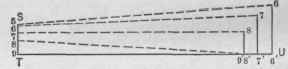
Fig. 702. - Diagram of Sections on Dotted Lines in A J H G of Fig. 700.
In Fig. 701 are shown the sections having the solid lines in A J H G as their bases, which are constructed in the following manner: Draw any right angle, as P Q R. Upon P Q set off the bights of the several points in the section A1 J1 from the line A1 B1, as measured upon the straight lines joining them with A1 B1; thus make Q 5 and Q 6 equal to the distance of points 5 and 6 from the line A1 B1. From Q on Q R, measuring from Q, set off the lengths of the several solid lines in A J H P, as indicated by the small figures, and from the points thus obtained erect perpendiculars equal in bight to the length of lines drawn from points of corresponding number in G1 H1 of the plan to the line G1 X; thus make the perpendiculars at points 5', 6', etc., equal to the length of the lines drawn from points 5 and 6 in G1 H1 to G1 X. Connect the points thus obtained with points of corresponding number in P Q. The oblique lines thus obtained will be the true distances represented by lines of corresponding number in the elevation. The diagram in Fig. 702 shows the sections upon the dotted lines in A J H G and is constructed in the same manner. Upon T U, .measuring from T, are set off the lengths of the several dotted lines. S T is the same as P Q of Fig. 701, and the perpendiculars at U are equal to those of corresponding number in Fig. 701. Points in S T are then connected with the perpendiculars of next higher number by dotted lines, which give the true lengths represented by the dotted lines of the elevation.
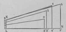
Fig. 703. - Diagram of Sections on Solid Lines in J B C D of Fig
That portion of the front piece shown by J B C D of the elevation must be triangulated in exactly the same manner as the portion just described, and sections constructed upon the several solid and dotted lines there drawn, as shown in Figs. 703 and 704. However, as no outline is given in either the plan or the elevation from which a correct stretchout of C D can be obtained, a section must be constructed for that purpose, which can be done in the following manner: First draw C1 M1 as the vertical center line of a rear elevation. From points C and D project lines horizontally to the right, cutting C1 M1 at C1 and M. Upon D M, measuring from M, set off half the width of the front piece at D2 of the plan; that is, make M D1 equal to M2 D2 Any desirable curve' may then be drawn from D1 to C1, representing the rear elevation of curve represented by D C of the side elevation. As the distance from C to D is much greater than C1 M, an extended profile, as measured upon C D, must now be developed from which to obtain a correct stretchout of that portion of the pattern.
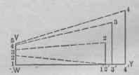
Fig. 704. - Diagram of Sections on Dotted Lines in J B C D of Fig. 700.
Continue to:
My Books

