Patterns For An Offset To Join A Round Pipe With One Of Elliptical Profile. Part 3
Description
This section is from the book "The New Metal Worker Pattern Book", by George Watson Kittredge. Also available from Amazon: The new metal worker pattern book.
Patterns For An Offset To Join A Round Pipe With One Of Elliptical Profile. Part 3
Therefore divide the curve C1 D1 into the same number of parts as the quarter circle B1 J1, and from the points thus obtained carry lines horizontally to the left, cutting C D. Upon C1 M extended, as C2 M1, set off spaces equal to those in C D, as shown, and through the points thus obtained draw lines to the left indefinitely. From the points in C1 D1 drop lines vertically, cutting those just drawn, all as shown. A line traced through the points of intersection, as shown from D2 to C2, will give the desired stretchout. In dividing the curve C D' into spaces it is advisable to make those nearest to D1 less than those near the top of the curve in order to compensate for the increase in the spaces in C2 M1 as they approach the bottom; thus obtaining a set of nearly equal spaces upon the final profile D2 C2, all of which will appear clear by an inspection of the drawing.

Fig. 705. - Hatf Pattern of Front Piece of Funnel Coat Hod.
As above stated, the diagrams of sections in Figs. 703 and 704 are constructed in the same manner as those of Figs. 701 and 702. The hights in K L and V W are taken from J1 B1 of Fig. 700 and are the same as those in P Q and S T of Figs. 701 and 702. The distances upon L N and W Y are those of the solid and dotted lines in J B C D of Fig. 700, and the hights of the perpendiculars near N and Y are equal to the lengths of the lines drawn from points of corresponding number in the profile D2 C2 of Fig. 700 to the lines C2 M1.
To develop the pattern of the front piece, first draw any line, as A G in Fig. 705, equal in length to A G of Fig. 700. From G as a center, with a radius equal to the dotted lines 9 8 of Fig. 702, describe a short arc (near 8), which intersect with another arc drawn from A as center, with a radius equal to 9 8 of the section A1 J1 B1 of Fig. 700, thus establishing the position of point 8 in the upper line of the pattern. From 8 of the pattern as center, with a radius equal to 8 8 of Fig. 701, describe a short arc (near 8'), which intersect with another arc drawn from G of the pattern as center, with a radius equal to 9 8 of the plan, Fig. 700, thus establishing the point 8' in the lower line of the pattern. Continue in this manner, using the lengths of the oblique dotted lines in Fig. 702 in connection with the spaces in the section A1 J1 B1 of Fig. 700 as radii to determine the points in the upper line of the pattern, or the side forming the mouth, and the lengths of the oblique solid lines of Fig. 701 in connection with the spaces in the plan of the bottom (G1 H1) as radii with which to determine the points in the lower line of the pattern or the side to fit against the bottom.
Having reached the points 5 and 5', next add to the pattern the flat triangular surface shown by J H D of the elevation. From H (5') of the pattern as center, with a radius equal to 5 5 of Fig. 706, the side of the last triangle in the pattern of the back piece, describe a short arc (near D), and intersect the same with another arc struck from J (5) of the pattern as center, with a radius equal to the oblique line 5 5 of Fig. 703, and draw H D and D J. Using D J of the pattern as one side of the next triangle, take as radii the distances 5 4 of Fig. 704 and 5 4 of the section D2 C2 of Fig. 700 to locate the position of point 4' of the pattern, as shown in Fig. 705. With 4 4 of Fig. 703, and 5 4 of the section B1 J1 of Fig. 700 as radii locate the point 4 of the pattern, as shown, and so continue until C D is reached. Lines traced through the points of intersection from B to A, C to D and H to G will complete the pattern of one-half the front piece.
The method of triangulating the piece forming the back of the coal hod and the development of the pattern of the same are so clearly shown in Figs. 706, 707 and 708, in addition to the plan and elevation, Fig. 700, as to need only a brief description. Divide H1 F1 and D2 E2 of the plan, Fig. 700, into the same number of equal parts, and from the points thus obtained erect lines vertically cutting the corresponding-lines H F and D E of the elevation, as shown by the dotted lines. Connect points of like number in that view by solid lines and points in DE with those of next lower number in H F by dotted lines. Since D E, being inclined, is longer than M2 E2, its equivalent in the plan, it will be necessary to develop an extended section upon the line D E of the elevation, as shown by D5 E3 of the plan, which may be done in the same manner as the section on the line C D above explained. Upon M2 E2 extended, as E2 E3, set off the spaces in D E, and through the points thus obtained draw lines at right angles, as shown, which intersect with lines drawn parallel with M2 E2 from points of corresponding number in D2 E2, thus establishing the curve D5 E3, from which a correct stretchout of the top of the back piece may be obtained.
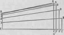
Fig. 706. - Diagram of Sections on Solid Lines in D E F H of Fig. 700.

Fig. 707. - Diagram of Sections on Dotted Lines in D E F H of Fig. 700.
In Figs. 706 and 707, the bights of the various points upon the perpendiculars from X and Z are equal to the lengths of the straight lines drawn from points of corresponding number in H1 F1 of the plan, Fig. 700, to the line M2 F1. The distances set off to the right upon the horizontal lines from X and Z are equal to the lengths of the several solid and dotted lines in D E F H of the elevation, and the hights of the perpendiculars at the right ends of the bases are equal to the straight lines drawn from points in the section D5 E3 to the line E2 E2 The several oblique solid and dotted lines are, therefore, the true distances represented by the solid and dotted lines of corresponding number in the elevation.

Fig. 708. - Half Pattern of Back Piece of Funnel Goal Hod.
In Fig. 708, E F is equal to E F of Fig. 700 and is made the base of the first triangle, from which base the several triangles constituting the complete pattern may be developed in numerical order and in the usual manner from the dimensions obtained in Figs. 706 and 707 and in the plan and section in Fig. 700, all as clearly indicated.
The pattern for the piece forming the foot of the coal hod is a simple frustum of an elliptical cone, the method of obtaining which is fully explained in Problem 171. In Fig. 540 of that problem the lines E F and G H are drawn much further apart than the proportions of the foot in the present case would justify, but the operation of obtaining its pattern is exactly the same
Continue to:
My Books

