Problem 108. Patterns For A Hip Molding Mitering Against The Bed Molding Of A Deck Cornice On A Mansard Roof Which Is Square At The Base And Octagonal At The Top
Description
This section is from the book "The New Metal Worker Pattern Book", by George Watson Kittredge. Also available from Amazon: The new metal worker pattern book.
Problem 108. Patterns For A Hip Molding Mitering Against The Bed Molding Of A Deck Cornice On A Mansard Roof Which Is Square At The Base And Octagonal At The Top
The problem presented in Fig. 415 is similar to that described in the previous problem, with the difference that a bed molding is introduced in connection with the planceer against which the hip molding is to be mitered. MEM1 represents a plan of the roof at the top, while L D M2 represents a horizontal line at the point A of the section, assumed at convenience somewhere between the top and the bottom for the purpose of measurement. The intersection of the lines M L and E D prolonged would indicate the corner of the building at the bottom of the roof, the structure being square at the base and octagonal at the top.
The first step in the development of the pattern is to obtain a correct section of the roof on the line of one of the hips. Therefore, at any convenient point lay off E3 D3 of Fig. 416 equal to D E of the plan. From the point E3 erect a perpendicular, E3 B2 in length equal to C B of the section of the roof. Con nect B2 and D3, which will be the pitch of the hip corresponding to the line D E of the plan. Since the section D3 E3 B2 has been constructed away from and out of line with the plan, it will be necessary to reproduce a portion of the plan in immediate connection with the section, as shown by I1 H A3 C2 This can be done by tracing, or any means most convenient. From the point H in this plan lay off on either arm the points I and I1, equally distant from it and conveniently located for use in constructing the profile of the hip molding. From the points I and I' erect perpendiculars to H C2, cutting it in the points K and O, which prolong until they meet the base D3 E3 of the diagonal section, from which points cany them parallel to the inclined line D3 B3 indefinitely. At right angles to the inclined line D3 B3 draw a straight line, O1 K1, cutting the lines last described in the points K1 and O1. From K1, measuring back on the line I2 K1, set off the point I2, making the distance from K1 to I2 the same as from K to I of the plan. From O1 in the line I1 I3 set off the distance O1 I3, equal to O I1 of the plan. From these points I3 and I2 draw lines meeting the line O1 K1 at the point of its intersection with the line D3 B2 Complete the profile of the hip molding, as indicated, laying off the width of the fascias on these lines, adding the roll and edges.
The next step in the development of the pattern is to draw a "true face" of the roof. In performing this operation it matters not whether the actual surface of the roof be used or the surface of the fascias. In this case the points A and B of Fig. 415, by which the depth and projections of the pitch are measured, are taken on the surface of the fascia. For the true face transfer the section A B to a vertical position, as indicated by A2 B1, Fig. 415, in connection with which the bed molding against which the hip molding is to miter is also drawn, as shown. From the several points in this vertical section draw horizontal lines, which intersect by vertical lines dropped from corresponding points in plan. Then D3 E3 X is the true face of that part of the roof corresponding to DEM1 M2 of the plan. In connection with the vertical section just described,' place a half profile of the hip molding, a true section of which has been obtained by the process already explained in Fig. 410, and also place a duplicate of this portion of the profile in connection with the true face. Space both of these profiles into the same number of parts, and from the several points in each carry lines upward parallel respectively to the lines of the views in which they appear; the lines from the profile in the vertical section cutting the bed molding, and the lines from the profile in the true face being continued indefinitely. From the points of intersection in the bed molding carry lines horizontally, intersecting those drawn from the profile in connection with the true face, producing the miter line, as shown by E2.
By inspection of the plan where a portion of the bed mold is shown it will be seen that the miter of the bed molding around the octagon at E is regular - that is, its miter line does not coincide with the line of the hip D E. If the profile of the bed molding in the vertical section, and also the profile of the bed molding as shown in the plan, be divided into any equal umber of parts, points may be dropped from the n profile of the plan on to the miter line E, and thence carried downward and intersected with horizontal lines from the corresponding points of the bed molding in section, also shown at E2, thus giving the appearance of the miter between the two arms of the bed mold behind their intersection with the hip roll. The vertical lines from the miter E of the plan have not been carried, in the engraving, further than E1, where they are intersected with lines from corresponding points from the profile at B of the elevation, thus showing how the operation is performed. This has been done to avoid a confusion of lines at E2. Having obtained this line in the true face, the point where it crosses the miter line between the hip mold and bed mold previously obtained at E2 must be noted. A line from this point of intersection must then be carried parallel to the line of the molding in the true face, back to the profile of the hip, and there marked, as shown by the figure 7 1/2. The position of the point 7 1/2 should now be marked upon the section of the hip molding previously obtained at O1 in Fig. 416. So much of the profile as exists between 1 and 7 1/2 in the true face is used in obtaining the stretchout of this part of the pattern. The remaining portion of the stay - namely, from 7 1/2 to 14 - is afterward used for the true face of the octagonal side for the remainder of the pattern.
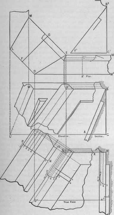
Fig. 415. - Plan, Elevation, True Face and Part of Pattern.

Continue to:
My Books

