Problem 153. Patterns For A Three-Piece Elbow In A Tapering; Pipe
Description
This section is from the book "The New Metal Worker Pattern Book", by George Watson Kittredge. Also available from Amazon: The new metal worker pattern book.
Problem 153. Patterns For A Three-Piece Elbow In A Tapering; Pipe
In Fig. 508 is shown a three-piece elbow occurring in taper pipe, in which the flare is uniform throughout the three sections. In solving this problem the simplest method will be to construct the elevation of the elbow and an elevation of an entire cone, from which several sections may be cut to form the required elbow, at one and the same time. Therefore in the elevation of the cone E F G let L1 M1 be drawn at a distance from E F equal to the total length of the three pieces measured upon their center lines, and also let its length be equal to the diameter of the elbow at its smaller end; then through E and L1 and through F and M1 draw the sides of the cone, intersecting in G.
At any convenient point, as B, draw the line B A at the angle which the axis of the middle piece is required to make with that of the lower (in this case 45 degrees), and bisect the angle ABC, as shown, by the line B D. Parallel with B D draw P R at any required hight, upon which locate the point I making P I equal to R J. (The reason for this is explained in the previous problem.) From the point I draw the axis of the second section of the elbow parallel with A B, making it (I H) equal to J G, and draw P H and R H. From any convenient point upon this axis, as U, draw U S at the required angle which the axis of the upper piece is required to make with that of the middle piece (in this case also 45 degrees, or horizontal), and bisect the angle S U I, as shown, by U T. Then the miter line N O can be drawn parallel with U T at any required distance from I, upon which locate the point i, making N i equal to O j. From i draw the axis of the upper piece of the elbow parallel with U S, making i K equal to j H. Next locate the line N O upon the original cone, making N' P equal to O R and O1 R equal to P N. Now make N L equal to N' L and M O equal to M1 O1 and draw M L
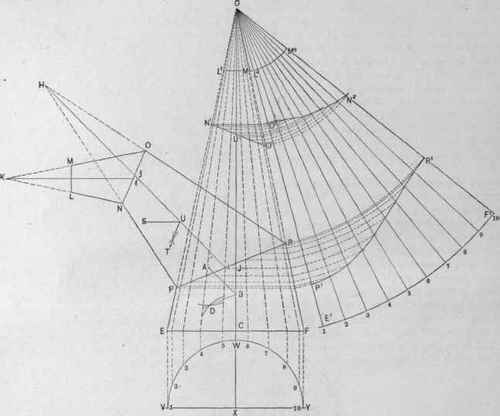
Fig. 508. - A Three-Piece Elbow in a Tapering Pipe.
It may be remarked here that on account of the shifting of the positions of the axes of the several pieces upon the miter lines by turning them, as shown by I J and i j, it will be impossible to ascertain with extreme accuracy the lengths of the various pieces upon their axes until the elevation E P NLMO R F is drawn, and therefore to obtain the position which the line M L will occupy.
This method of solving the problem is given upon the supposition that its simplicity will compensate for this slight inaccuracy, as usually differences of length can be made up in the parts with which the elbow may be connected. If the lines M L and E F are to be assumed at the outset as fixed factors between which a tapering elbow is to be constructed, it will be somewhat difficult to ascertain the exact dimensions of a cone, E F G, which can be cut and its parts turned so as to constitute the required elbow. Hence, while two of the pieces (say the two lower ones) can easily be cut from an entire cone assumed at the outset, the third piece will have to bo drawn arbitrarily to fit between the last miter line N O and the small end M L, and will very likely be of different flare from that of the other two pieces. This will necessitate the last section being cut by the method of triangulation, problems in which are demonstrated in Section 3 of this chapter, to which the reader is referred.
Saving, as explained above, obtained the lines of cut through the cone, the patterns may be described as follows: Draw the plan V W Y, its center X falling upon the axis of the cone produced, which divide in the usual manner into any convenient number of equal parts. Through the points thus obtained erect perpendiculars to the base E F, and thence carry lines toward the apex G, cutting the miter lines P R and N1 O1. With the T-square at right angles to the axis G.C, and brought successively against the points in N1 O1 and P R, cut the side G F of the cone, as shown by the points above 0' and below R. From Gas center, with radius G F, describe the arc E1 F1, upon which lay off the stretchout of the plan V W Y, as shown by the small figures 1. 2, 3, etc., and from these points draw measuring lines to the center G. From G as center describe arcs corresponding to the distance from G to the several points established in G F, which produce until they intersect lines of corresponding numbers drawn from the center G to the arc E1 F1. Through these points of intersection trace lines, as shown by O2 N2 and P1 R1. From G as center, with radius G M1, describe the arc L2 M1. Then L2 M2 N3 O2 is the half pattern of the upper section, O2 N2 R1 P1 that of the middle section, and P1 R1 F1 E1 that of the lower section.
Continue to:
My Books

