Chapter XLI. Miscellaneous Patterns. Gear Case For Mitre Wheels
Description
This section is from the book "Practical Sheet And Plate Metal Work", by Evan A. Atkins. Also available from Amazon: Practical Sheet And Plate Metal Work.
Chapter XLI. Miscellaneous Patterns. Gear Case For Mitre Wheels
The making of a sheet metal covering to act as a guard for bevel wheels is not by any means a difficult matter, the chief consideration being the setting out of the patterns to work up exactly to the required shape. A view of a pair of wheels is shown in Fig. 339, the thick dotted lines representing the gear case. A little consideration will show that the guard is formed from the surfaces of four cones, arranged in such a way to intersect or cut into each other so as to give the necessary opening for the two wheels to gear together. The setting out of the patterns is fully explained by the diagrams on Fig. 340.
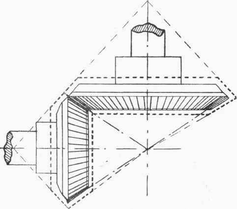
Fig. 339.
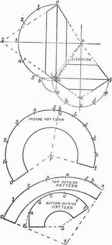
Fig. 340.
The case is made in two equal halves, these, when put over the wheels, being fastened together with slip wire hasps at f and o. It will thus be seen that each half of the cover is formed of four half frustums of cones.
The inside cones have a common apex at p, and overlap or intersect each other so as to give the opening for the two wheels to come together. Thus, the base of one cone is f h and the other o m, these crossing at x. In setting down the bases of the cones the sizes of these must be arranged so as to bring the lines x 6 and x a equal in length, these giving half the width of the opening of the cones at the bases.
In marking out the pattern for the insides of the case, P o on the pattern is made equal to p o on the elevation; the lengths 0 1, 1 2, etc., up to 6, being set off from the top semicircle, and the lengths a b, b c, etc., from the bottom semicircle.
The patterns for the outside are marked out in a similar manner, T o and S f on the patterns being equal, respectively, to t o and s f on the elevation. The girth around each one will be the same length as that of the corresponding semicircle in the elevation. The straight lines at the ends are obtained by seeing that M 6 and H a on the patterns are respectively the same lengths as the arcs m 6 and h a on the elevation, the lines then being drawn square to the outside lines of the patterns. It should be observed that these two lines come the same length if the patterns are marked out correctly.
Half discs to put into the backs and fronts of the casing will be required, but patterns for these are not shown. Allowances for jointing must be added to the patterns to suit the method of jointing adopted.
Continue to:
My Books

