Construction And Management Of Gasoline Engines. VII. Spark Coils-Wiring: Diagrams
Description
This section is from the book "Amateur Work Magazine Vol6". Also available from Amazon: Amateur Work.
Construction And Management Of Gasoline Engines. VII. Spark Coils-Wiring: Diagrams
Carl H. Clark
Coils
Coils for use with gasoline or gas engines are of two kinds, the plain coil illustrated in Fig. 40, and the induction coil shown in Fig. 41. The former is used in connection with the make and break ignition, and the latter with the jump spark system.
The plain coil shown in Fig. 40, consists of a core or bundle of soft iron wires C, surrounded with a coil, W, of rather coarse wire. While only one layer is shown, there are in reality several layers, one over another.

Fig. 40.
The ends, E E, are of wood, and hold the binding posts, B B, to which the ends of the coil of wire W are fastened. The complete spark coil will thus be seen to consist simply of a continuous coil of wire surrounding the iron core. The coil is introduced into the battery circuit, and the current simply passes through it. As to the electrical action of the coil, it will be sufficient to say that the passing of the current around the iron core greatly intensifies the spark at the breaking of the circuit.

Fig. 41.
Fig. 41 shows a diagram of a jump spark or induction coil. This coil is quite similar in principle to the ordinary induction or medical coil. It consists of a core of soft iron wire, surrounded by a primary winding, P, made up of two or three layers of coarse wire. Outside of this winding, and thoroughly insulated from it, is the secondary winding S, made up of many turns of very fine wire. Each time that the current is made or broken in the primary coil a corresponding current tends to flow in the secondary. If, then, the terminals of the secondary coil are connected to a spark plug, a spark will pass each time the circuit is made or broken in the primary. The terminals of the primary coil are connected to the binding posts B B, and those of the secondary to the posts, P P. During action of the coil, the iron core is alternately magne-
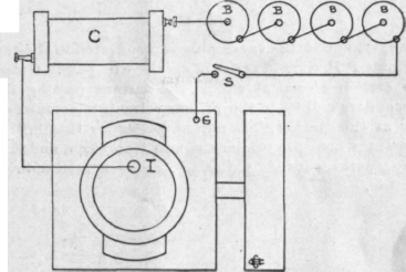
Fig. 42.
tized and demagnetized by the passage of the primary current. The vibrator spring V is fastened at its lower end, and on its upper end carries the iron disc d, which stands opposite to and a short distance away from the end of the iron core. The vibrator adjusting screw A bears against the vibrator V. One terminal of the primary is connected to the adjusting screw A, and the stationary end of the vibrator is electrically connected to one of the binding posts, B. If, then, the battery terminals are connected to the posts B B, a continuous circuit is formed through the vibrator spring, adjusting screw and primary coil, allowing the current to flow through the primary coil, and by induction setting up a current through the secondary coil.
The flowing of the current around the iron core magnetizes it and causes it to attract the iron disc or armature d, thus drawing the vibrator out of contact with the adjusting screw A and breaking the circuit, causing a current to pass through the secondary in the opposite direction. The breaking of the primary current also causes the demagnetization of the iron core, releasing the disc d and allowing the vibrator to spring back into contact with the screw A, again completing the primary circuit and allowing the previous action to be repeated. This automatic interruption of the primary circuit, which is extremely rapid, causes a series of alternating currents to pass through the sec-

Fig. 43.
ondary, and if the spark plug is connected to the terminals P P, a rapid series of sparks will pass. Owing to certain electrical effects, the current passing the secondary coil when the primary circuit is completed, or at the "make," is not as strong as that which passes when the primary circuit is broken, and it is the sparks caused by the latter which is visible in action.

Fig. 44.
The current in the primary circuit is of small voltage and of relatively larger volume, while that in the secondary is of extremely high voltage and of small volume. The relative proportions of the two are regulated by the size and amount of the wire in the two coils.
A condenser is shown at C, consisting of layers of tin foil, insulated from each other, alternate sheets of which are connected to two terminals, which terminals are connected, as shown, with the vibrator screw and the terminal B. The electrical action of the condenser need not be dwelt upon here, except to say that it greatly intensifies the spark at the "break." The entire coil is enclosed in a box with only the binding posts and vibrator in sight.
Batteries
The ordinary form of dry battery or some form of liquid battery may be used, as desired. The latter are supposed to be more reliable than the former, and certainly do cost less in the long run. Dry batteries are, however, much less troublesome to handle, are more convenient, and may be depended upon with a reasonable degree of certainty if well taken care of. It is always advisable to fit batteries in duplicate sets, either of which may be used
On an engine of any considerable size, batteries should not be depended upon for continuous running, but a magneto should be used except for starting, allowing the batteries to retain their strength. A double throw switch serves to throw in or out either battery or magneto. Batteries are connected in series, the zinc of one cell with the carbon of the next, and so on.
Accumulators
Storage batteries may be used, but are as yet little used in marine work. They are especially useful where a miniature lamp or two is desired, to facilitate handling the boat at night, as when coming to a mooring, as the lighting circuit can be taken from the same battery that is used for sparking the engine.
Continue to:
My Books

