Construction And Management Of Gasoline Engines. X. Reversing Gears
Description
This section is from the book "Amateur Work Magazine Vol6". Also available from Amazon: Amateur Work.
Construction And Management Of Gasoline Engines. X. Reversing Gears
CARL H. CLARK
The gasoline engine, unlike the steam engine, has no ready means of reversing. Although most two cycle and some four cycle engines will run in either direction, the means of accomplishing it are cumbersome and not always certain, borne few engines have permanent reversing gears which work fairly well, but the majority of engines must practically be stopped and

Fig. 68 started in the opposite direction. It is possible to reverse a two cycle engine by a proper manipulation of the timing of the spark, as will be explained under the handling of engines; it is, however, not to be relied upon. This fact and the fact that most four cycle engines run in one direction only, necessitates the adoption, of some form of outside reversing device. Engines of small power fitted in light boats can be run without any reversing device, but engines of over four or five horsepower should always be so fitted.
The simplest form of reversing device is the reversing propeller, which is fitted with a device for twisting the blades, to the reverse angle, causing the propeller to act in the opposite direction with the shaft always turning one way. Fig. 68 shows a sketch of a
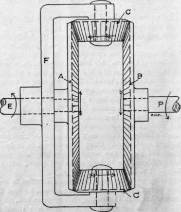
Fig. 69 two blade reversing propeller. The shaft is made hollow, with the rod R moving longitudinally inside of it. This rod is round inside of the shaft and square in the propeller hub. On one side of the square end of the rod is the groove a running diagonally across it. The blade b, is provided with the collar c, which fits under the projections d of the hub, holding the blade in place, while allowing it to turn. The face of the collar C bears snugly against the flat of the rod R. On the under face of the collar c is a pin P which projects down and fits into the slot a. It will thus be seen that if the rod R is moved along the shaft the pin P will slide in the slot A and thus turn the blade of the propeller. When the rod is in its extreme right hand position, the pin P will have moved to p, having swung across the center line into the opposite position and causing the blade to take an angle opposite to its former one and

Fig. 70 to exert its force in the opposite direction. At some point about midway between tnese two, the blades will be practically at right angles to the shaft, and will turn without exerting any force. By turning the blades slightly either way a slight force will be exerted. Thus all speeds may be obtained, from full speed either way down to nothing. This allows the boat to be easily handled and even stopped entirely, without touching the engine.
The other blade is on the opposite side of the hub, and is operated by a pin in a slot on the opposite side of the flat end of the rod R and both blades turn together. The driving shaft S is hollow for the rod R and on its inboard end has an attachment to allow the rod R to be moved back and forth.
This form of propeller is a cheap and fairly satisfactory way of controlling the speed. If properly constructed it is nearly as strong as a solid wheel; the majority of reversible wheels on the market today are, however, poorly disigned and of flimsey construction and care must be taken in the selection of such a wheel. It should also be stated that the shape of the blade can be correct for one position only, and for all others it is more or less unsuited. For this reason, unless the correct position happens to be hit upon for the full speed, a certain loss of power is apt to follow. A reversible blade propeller is thus very likely to waste more power, and give less speed than a solid propeller.
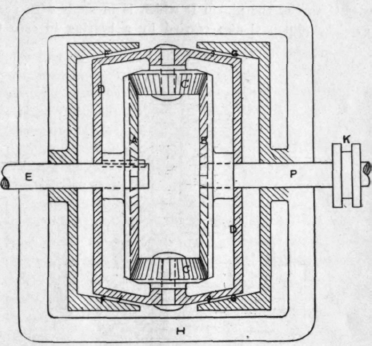
Fig. 71.
For engines of over six horse power a reversing device of the geared type must be used. These may for the present purpose be divided into two types, those using bevel gears and those using spun gears. Fig. 69 shows a diagram of the former type. The engine shaft E carries the large bevel gear A and the propeller shaft P carris a similar gear. The frame F encircles the shaft E and has bearing carrying the bevel pinnons C which mesh with the gears A and B. The frame F has two locking devices, one of which locks it to the shaft E and causes it to revolve with it. The other device locks it to the engine frame, holding it stationary and allowing the shaft E to revolve independently.
Suppose now that F is locked to the shaft E and turns with it, the gears C and A are thus locked together, and in consequence the entire gear revolves together and the shafts E and P turn in the same direction. This is the forward speed. If, now, the frame F is unlocked from the shaft E and locked to the engine bed so that it cannot turn, the gears C. C. will be brought into action. If the shaft E continues to revolve as shown by the arrow, th gears A-C-B will turn in the direction of the arrows and the shaft P will turn, as shown by its arrow, in the opposite direction to E. This is the reverse motion.
Suppose now that the frame F is left free, the shaft E may turn and the gears C will simply roll around on B without turning it, and the shaft P will remain stationary. This allows the boat to be stopped without stopping the engine and also permits the starting of the engine without the labor of turning the entire shafting and propeller.
Fig. 70 shows a diagram of the spur gear type of reversing gear. The engine shaft E carries the gear A while the propeller shaft P carries the gear B. These are enclosed in a case G. A bearing on the side of case G carries the pinion D which is in mesh with gear A. The pinion C also carried by a bearing in case G

Fig. 72.
meshes with pinion D and also with gear B. There is thus formed a complete connection between gears A and B. As before, the case G is arranged to be either connected to revolve with shaft A or to remain stationary. Suppose now that case G is locked to the engine shaft A. This locks the gears inside of the case and drives A and B together thus driving the propeller shaft in the same direction as the engine shaft. Suppose now that the case G is released from the shaft E and prevented from turning by locking to the engine frame. The gear A causes the pinions D and C to revolve, thus revolving the gear B and shaft P, but in the opposite direction to that of shaft E. If the case G is left free, while the shaft E is turned it will simply revolve idly without moving the gear B thus allowing the engine to run idly as before.
It should be noted that the gear described in Fig. 69 reverses the propeller shaft at the same speed as the engine shaft while in that of Fig. 70 the reverse motion is slower than the forward motion in the proportion of the diameters of the gears A and B. The radius of A is reduced by the diameter of the idle gear D which gear is necessary to produce the reverse motion. This difference in speed is of little account, as a reverse at full speed is seldom necessary.
Fig. 71 represents the application of the bevel gear reverse. The bevel gears are contained in a sort of cast iron case or drum D which has bearings for the gears C-C. The outside of the drum D has the two conical friction surfaces f and g. The two pieces F and G have

Fig. 73.
corresponding conical surfaces fitting f and g. The piece F is fastened to and revolves with, the shaft E while G is stationary and fastened to the base H. The gear A is not rigid on the shaft E but is fitted over a spline or key, which allows the gear to move along the shaft and still be driven. The drum D is a running fit on the shafts E and P allowing them to turn easily. A fork fitting into the grooved collar K, allows the shaft P and the drum D to be moved slightly. Suppose it to be moved to the left, bringing the conical friction surfaces F and f into contact. This locks the drum D to the shaft E thus locking the gears inside and driving the shaft P direct. When in the position shown the drum D is free to revolve either way, and whatever may be the motion of the engine shaft, no motion of shaft P will result, as the gears O.C. Will simply roll around on gear B without causing any motion. Suppose again, that the shaft P and drum are moved to the right, bringing the friction surfaces G and g into contact. Since G is stationary the drum will become stationary and the gears will come into play, producing the reverse motion as before described. The slight fore and aft motion is allowed by the leather in gear A without drawing the gears out of mesh.
Pig. 72 shows a spur gear reversing clutch similar to that of Fig. 70 but using an internal gear. E is the engine shaft carrying the spur gear A. A shallow case D, which is loose on the shaft E, carries the pinions C. C. Two pinions are provided to distribute the wear. This case D is provided with the conical friction sur-face F on the inside of its rim, and the parallel friction surface G on the outside of the rim. The propeller shaft P also carries a shallow drum H, having on the outside of its rim a conical friction surface fitting into that on D and on the inside an annular gear B which meshes with the pinion C. A fork fitting into the grooved collar L allows the shaft and drum H to be moved fore and aft. A friction band K. on the outside of drum D is tightened by a wedge and holds the drum stationary when desired. Suppose the shaft P and drum H to be moved to the left; this will bring the friction surfaces F and f into contact, locking the gears, and driving everything together in the same direction. As shown in the sketch the drum D is entirely free and the shaft E may turn without turning the engine shaft. If, however, the friction band K is tightened the drum D will remain stationary, the gears will come into action and the shaft P will reverse.
In another form of gear, the engine shaft carries a sprocket and chain C, the drum D carries a bearing for the gear A to which is fastened the other sprocket of the chain C. The propeller shaft carries spur gear B similar to A. At F is a friction surface for connecting with the shaft when the tapered collar G is moved to the right, the levers L are pressed out and the friction band F is expanded, driving the whole with the shaft. As shown the gear is in the free position. The friction f is tightened by a wedge. When tills done, the drum D remains stationary and the drive is through the chain and gears producing a reverse motion of shaft P.
The prime requisites of any reverse gear are that the gears should be in mesh at all times to avoid stripping, they should also run in oil, to reduce wear. It must be so arranged that the two frictions cannot be put in action together which would damage the gear. The gears should be in action only in reverse motion.
All reversing gears will be found to embody one or more of these principles and with this explanation no difficulty should be found in understanding the action of any type of reversing gear.
Continue to:
My Books

