Mercury Arc Rectifiers
Description
This section is from the book "Amateur Work Magazine Vol6". Also available from Amazon: Amateur Work.
Mercury Arc Rectifiers
Joseph Alden
A new device has been put upon the market within the last few years for converting alternating current into direct current. This is the mercury arc rectifier. It is quite probable that the readers of this magazine are more or less familiar with its peculiar, greenish light, as they are in use in garages, and many private residences where the electric automobile is used and only alternating current is available. Its chief use at present is the charging of storage batteries, which it does to a degree of nicety that is remarkable, and its high efficiency has reduced the cost of charging considerably.
has a very high resistance. Nevertheless if the vapor becomes electrified or "ionized," it becomes a good conductor, but allows the passage of current in only one-direction and that towards the terminal immersed in mercury. Only a few volts are required to sustain this passage after it has been started, but the starting of the arc was a puzzle for a long time to the experimenters. They finally discovered that if a spark was produced between a terminal and the mercury the vapor would be sufficiently ionied to start and sustain an arc from. the main anodes. The starting anode was therefore inserted, and by a slight shake contact is made and bro-
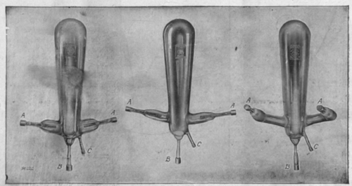
Fig. 1.
The prominent and most important part of the outfit is the mercury tube, which is a glass vessel from which the air has been exhausted. Into this protrude four terminals or electrodes-one at the bottom, one a little way up the side, and the other two on opposite sides and well up on the tube. The electrode at the bottom is covered with mercury, and the one on the side is just high enough so that the mercury will not touch it when the tube is vertical. The terminal at the bottom is the cathode, the one part way up the side the starting anode and the two well up on the sides the main anodes. Fig. 1 is the type of mercury tube manufactured by the General Electric Co.; A, A are the main anodes, B the cathode and C the starting anode.
Although mercury itself is an excellent electric conductor, mercury vapor, produced in vacuum by heat, ken between it and the cathode giving the necessary spark.
To understand the working of the mercury tube, a conception of the nature of alternating current is necessary, so the following explanation is given for the benefit of those not familiar with it. Any complete circuit, whether alternating or direct current, requires two wires. Let these be numbered 1 and 2. An alternating current is one which first goes out on wire No. 1, coming back on wire No. 2; and then goes out on No. 2 and back on No. 1; that is, it alternates in direction between wires No. 1 and No. 2. Two of these alternatious or reversals make a complete cycle, and the number of complete cycles per second is called the frequency. The most usual frequency for lighting at present rate is 60 cycles per second.
The two wires of the circuit are connected to the anodes, and one end of the direct current load is connected to the cathode. As stated before, the ionized mercury vapor allows the current to pass through it in only one direction, so when the current comes on wire No. 1 it passes into the tube at A (See diagram No. 2) and when it comes on wire No. 2 it passes in at A*. It can be seen therefore that half the alternations goes through from one anode and the other half from the other anode. As only half goes through at a time the direct current voltage will be approximately one-half the alternating current voltage. Theoretically this should work, but experiment has shown that there is
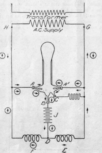
Fig. 2.
sufficient time between the alternations (at the turning point of course the voltage is zero) for the vapor to lose its excitation and the tube would go out. Experimentation was carried on to find if possible a frequency that would work, but the tube would go out with a current having 10,000 cycles.
It was necessary, therefore, to put something in the circuit to bridge the zero point and the two coils F and E, were introduced. These have what is termed capacity, that is, they can store up voltage while the main current is increasing, and discharge it into the tube while the main voltage is at zero. The other terminal of the direct current load is connected between the reactances. The operation of the complete rectifier outfit can now be explained by diagram No. 2. In this the two directions of the alternating current are represented, one by a plain arrow and the other by an arrow in a circle.
The current can be assumed as first starting from H, and is shown by the plain arrow. It passes into the tube at A, out at C, to the load V, through the reactance E, thence back to the source. Reactance E stores some of the current, and when the main current comes to zero it discharges into the tube at A1, serving to keep the tube going until the main current builds up again in the opposite direction, as shown by the arrow in the circle. The operation is thus repeated for the other

Fig. 3.
alteration, using reactance F, and a cycle is completed. This action repeats for every cycle in the alternating current.
A resistance is connected between the starting anode and the line, which allows just enough current through to start, but prevents a short circuit. Various devises are introduced into the circuit for the control and regulation of the output.
Theoretically this rectifier should have an efficiency of 100 per cent.; that is, the volts, X the amperes, direct current, or power, should equal the volts X the amperes, alternating. This is not so, however, due to a slight loss in the reactance, and also to the fact that it requires a certain number of volts to maintain the current in the tube. The efficiency obtained, however, is in the vicinity of 75 or 80 per cent, for high D. C.
voltages, which is very good and very much better than any other small converting outfit.
Although it is used mostly for charging storage batteries, it is also being used to run lights, small motors, and similar work. It is necessary, however, to keep a small constant load on the tube all the time it is in use, •as it would go out if the motor, for instance, was shut line to get fine variations in voltage. Beneath the panel is the main reactance. The back view shows the tube and series controlling reactance mounted on back of the panel.
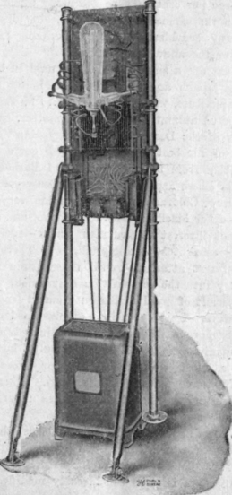
Fig. 5 shows the connections of this panel, the diametric location of all the different devises; and also a table of connections, whereby it is possible to obtain many different D. C. voltages.
Since the D. C. voltage is about a half the A. C. voltage, the D. C. current is about twice the A. C. current. The 75 to 80 per cent, efficiency is obtained only where nearly the maximum D. C. voltage is used. The efficiency will, therefore, go down as the D. C. voltage down or lights turned off. The General Electric Co. is making small outfits for running direct current dental motor drills, the size being very handy for experimental work as well.
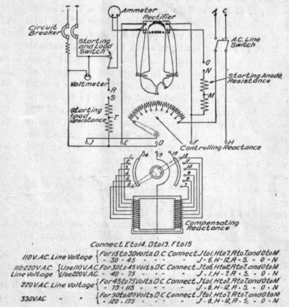
Fig. 4.
Fig. 5.
Figs. 3 and 4 show the front and back view of a Mercury Arc Rectifier Panel, made by the General Electric Co. for charging storage batteries. With 110 volts A. C. it will give 40 Ameperes at about 46 volts D. C.; with 220 volts A. C, 40 Amperes at about 115 volts D. C.; and with 330 volts A. C, it will give 40 Amperes at 175 volts D. C.
The instruments on the panel are as follows: at the top, the circuit breaker in the D. C. lines, next the voltmeter and ammeter, then a hand wheel for shaking the tube; which is mounted on the back. On the next line the switch at the left controls the A. C. line, and the switch at the right is for starting. Next it a series controlling reactance, which is inserted in the A. C. is lowered, as it is impossible to raise the current beyond the tube capacity. There are four sizes of tubes, 10, 20, 30 and 40 amperes. An attempt to take more than the rated current would heat the anodes and break the tube.
Continue to:
My Books

