A Pocket Direct - Current Voltmeter
Description
This section is from the book "The Boy Mechanic Vol. 2 1000 Things for Boys to Do", by Popular Mechanics Co.. Also available from Amazon: The Boy Mechanic, Vol2: 1000 Things for Boys to Do.
A Pocket Direct - Current Voltmeter
The assembled drawings of a very simple voltmeter are shown in Fig. 1, and its operation is as follows: The moving portion consists of a pointer, or needle, A; a small permanent magnet, or armature, B, and a counterweight, C, mounted upon a small steel shaft, D. The ends of this steel shaft are pointed and rest in bearings provided in the U-shaped piece of brass E, which is rigidly fastened to the fiber base F, by means of two screws. The permanent magnet B, carried on the shaft D, is at all times under the magnetic influence of the permanent horseshoe magnet, G, which is fastened, by means of thin brass straps, H H, and small screws, to the base F, so that the ends of the armature B are directly above the poles of the horseshoe magnet. The armature B will assume the position shown in the sketch when it is acted upon by the permanent magnet G alone and the moving system is perfectly balanced. A solenoid, J, is mounted in the position shewn. When there is a current in its winding its soft-iron core will become magnetized and the magnetic pole produced at the lower end will produce a magnetic force upon the armature B, with the result that the armature will be rotated either in a clockwise or counter-clockwise direction, depending upon its polarity and the polarity of the end of the core adjacent to it. Thus, if the left end of the armature has north polarity, the right end south polarity, and the lower end of the core is magnetized to a south polarity the armature will be rotated clockwise, for the left end, or north pole, will be attracted by the lower end of the iron core, which is a south pole, and the right end will be repelled. This is in accordance with one of the fundamental laws of magnetism which states that magnetic poles of unlike polarity attract each other and those of like polarity repel each other. The amount the armature B is rotated will depend upon the relative effects of the pole of the solenoid and the permanent magnet G. The strength of the pole of the solenoid will depend upon the current in its winding and the number of times the current passes around the core, or the number of turns in the winding. In other words, the strength of the pole of the solenoid varies as the product of the current and the number of turns, which is called the ampere-turns. The same magnetic effect can be produced by a large current passing through a few turns or a small current passing through a relatively large number of turns. This simple relation of current and turns gives a means of adjusting the current capacity of the instrument so that a full-scale deflection of the needle will correspond to any desired maximum current. The instrument may be used as either a voltmeter or as an ammeter, and its operation will be identical in each case. The resistance of the voltmeter, however, will be many times the resistance of the ammeter, as it will be connected directly across the line, while the ammeter will always be in series in the circuit in which it is desired to measure the current. The following description and suggestion as to how to proceed in the construction of this instrument may be useful to those who undertake to build one. All the minor details and some of the dimensions will be omitted in the description, but these can be easily supplied. Procure a piece of hard rubber or fiber, about 1/4 in. in thickness and of sufficient size to cut from it a disk, 2 1/2 in. in diameter. Make a small horseshoe magnet from a piece of the very best steel obtainable, and magnetize it to as high a strength as possible. This magnet is made of a piece of steel, 1/8 in. thick, about % in. in breadth, and of such length that the overall lengthwise dimension of the completed magnet will be about 1% in. and the distance between the inside edges of the ends a little greater than 1/2in. Fasten the completed magnet to the base F by means of two or three straps, made from some thin brass, and small machine or wood screws.

Ill: The Parts as They are Assembled to Make a Pocket Voltmeter for Direct Currents
Then cut from some 1/16-in. sheet brass a piece having the general appearance and dimensions shown at A, Fig. 2. Bend the ends of this piece over at right angles to the center portion along the dotted lines. Drill the hole at the upper end and thread it for a 1/16 machine screw. By means of a pointed drill, make a small recess at the lower end directly opposite the first hole. This small recess is to form the lower bearing for the shaft supporting the moving system, while a small recess cut centrally in the end of a screw, mounted in the upper hole, will form the upper bearing. The screw placed in the upper hole need be only about 3/16 in. long. The holes in the two wings are for mounting this piece upon the fiber base, as shown in Fig. 1.
The shaft for supporting the moving system is made of a piece of a hatpin. It is about 13/16 in. long and its ends are pointed so that they will turn freely in the bearings provided for them.
The armature is cut from a piece of 1/16-in. sheet steel. It is made about 3/4 in. long, 5/16 in. wide at the center, tapering to 1/8 in. at the ends. A hole is drilled in its center so that it may be forced onto the shaft. It is mounted so that its lower surface comes about 1/4 in. from the lower end of the shaft.
Then cut from some very thin brass a piece, that is to form the needle, 1/4in. wide at one end and tapered to a point at the other, the total length being about 3 in. Drill a hole in the large end of this piece, the same size as the shaft and 1/2 in. from the end.
This piece is not fastened to the shaft until some of the other parts are completed.
The spool upon which the winding is to be placed is made as follows: Procure a piece of very soft wrought iron, 1 1/4 in. long and 1/4 in. in diameter, to form the core. The ends of the spool are made of thin brass and are dimensioned as shown in Fig. 2, at B and C. The piece shown at B is to form the lower end of the spool, and is bent at right angles along the dotted line. The two holes at the lower edge are for attaching the end of the spool to the fiber base. The piece shown at C forms the upper end of the spool and at the same time a back upon which the scale of the instrument is mounted. The holes in the lower edge are threaded for small machine screws, as it will be necessary to fasten this piece to the base by means of screws that pass through the base from the under side, as shown in Fig. 1. Bend the upper and lower portion of the piece over at right angles to the center portion along the dotted lines. Make sure that the large hole in the center of each end piece is of such size that it will fit very tight on the end of the wrought-iron core. Force the end pieces onto the ends of the core a short distance, say, 1/16 in., and hammer down the edges of the core so that the end pieces cannot be easily removed. In Fastening the ends to the core be sure that the parts that are to rest upon the base are parallel with each other and extend in opposite directions; also that the ends are at right angles to the core. Then insulate the inner portions of the completed spool with several thicknesses of onion-skin paper, or any good-quality, thin writing paper, and shellac. The winding will be described later.
Mount the spool and support for the bearings upon the base so that they occupy the positions, relative to each other, indicated in Fig. 1. A paper scale is then mounted upon the brass base provided for it by means of some thin shellac. The upper and lower lines for the scale can now be drawn upon the paper, using the center of the screw at the lower end of the needle as a center. These lines are best placed about 1/8. apart and not nearer the edge of the base than 1/4ches.
The needle is bent over at right angles 5/16 from the center of the shaft. Another right-angle bend in the needle is then made so that the pointed end will be about 1/16 above the surface of the scale when the large end of the needle is fastened to the shaft % in. from the upper end of the latter. Turn the needle on the shaft so that the pointer is at the left end of the scale when the moving system is at rest. The shaft must be exactly vertical when this adjustment is made. Cut the end of the needle down until its end is midway between the two scale lines. Solder the needle to the shaft, and then place a sufficient quantity of solder on the broad end to balance the system perfectly and allow it to come to rest in any position when the armature B is not influenced by any magnetic field.
A containing case for the instrument may be made as follows: Make a cylinder from some thin sheet brass, having exactly the same inside diameter as the base, and a height a little greater than the vertical distance from the lower surface of the base to the upper surface of the needle. Also a disk from some thin sheet brass, having a diameter 1/8- greater than the outside diameter of the cylinder. Round off the edges of this disk and cut a curved slot in it directly over the scale, about % in. wide and of the same length and form as the scale. Solder the disk to one end of the cylinder, placing the solder all on the inside. To prevent moisture from entering the case, fasten a piece of thin glass on the under side of the slot in the disk by means of some shellac and several pieces of brass soldered to the disk and bent down onto the glass. The case can now be fastened to the base by means of several screws, passing through its lower end into the edge of the base. Two small binding posts are mounted on the outside of the case, about 90 deg. apart and well insulated from each other and from the case.to serve as terminals for the instrument.
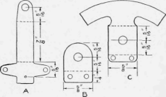
Ill: Fig 2 Details of the Supports for the Coil and for the Needle, or Pointer. Shaft
The instrument is now complete with the exception of the winding. Since this is to be a voltmeter and it is always desirable that a voltmeter take as small a current as possible, the winding must consist of a relatively large number of turns of small wire, each turn carrying a small current. The difference in the construction of different instruments necessitates that their winding contain a different number of turns in order that a given voltage may produce a full-scale deflection. A little experimenting with different windings is the easiest means of determining the proper size of wire and number of turns to meet individual requirements. After adjusting the winding so that the maximum voltage it is desired to measure produces a full-scale deflection, the scale is calibrated by marking the positions of the needle in accordance with those of the needle of a standard instrument connected in parallel with it. In marking the scale of an ammeter, connect the instruments in series. Remember that if the instrument is to be used as an ammeter, it must have as low a resistance as possible and that to prevent undue heating, the wire must have ample cross section.
If difficulty is experienced due to the continuous vibration of the needle, although the current be practically constant, this trouble can be greatly reduced by mounting a paper wind vane on the moving system, which will tend to dampen its movement.
Continue to:
More:
- Needle Box for Talking Machines
- A Cover Strainer
- Toy Parachute Cut-Away for Kite Lines
- Houses Made of Poles
- Homemade Hinges For Boxes
- Frosting Brass
My Books

