How To Make A Jump-Spark Coil
Description
This section is from the book "The Boy Mechanic Vol. 1", by Popular Mechanics Co.. Also available from Amazon: 700 Things for Boys to Do.
How To Make A Jump-Spark Coil
The induction coil is probably the most popular piece of apparatus in the electrical laboratory, and particularly is it popular because of its use in experimental wireless telegraphy. Ten years ago wireless telegraphy was a dream of scientists; today it is the plaything of school-boys and thousands of grown-up boys as well.
Divested of nearly all technical phrases, an induction coil may be briefly described as a step-up transformer of small capacity. It comprises a core consisting of a cylindrical bundle of soft-iron wires cut to proper length. By means of two or more layers of No. 14 or No. 16 magnet wire, wound evenly about this core, the bundle becomes magnetized when the wire terminals are connected to a source of electricity.
Should we now slip over this electromagnet a paper tube upon which has been wound with regularity a great and continuous length of No. 36 magnet wire, it will be found that the lines of force emanating from the energized core penetrate the new coil-winding almost as though it were but a part of the surrounding air itself, and when the battery current is broken rapidly a second electrical current is said to be induced into the second coil or secondary.
All or any of the parts of an induction coil may be purchased ready-made, and the first thing to do is to decide which of the parts the amateur mechanic can make and which would be better to buy ready-made. If the builder has had no experience in coil-winding it would probably pay to purchase the secondary coil ready-wound, as the operation of winding a mile or more of fine wire is very difficult and tedious, and the results are often unsatisfactory. In ordering the secondary it is always necessary to specify the length of spark desired.
The following method of completing a 1-in. coil illustrates the general details of the work. The same methods and circuits apply to small and larger coils. The ready-made secondary is in solid cylindrical form, about 6 in. long and 2-5/8 in. diameter, with a hole through the winding 1-1/4 in. in diameter, as shown in Fig. 1. The secondary will stand considerable handling without fear of injury, and need not be set into a case until the primary is completed. The primary is made of fine annealed No. 24 iron wire cut 7 in. or 8 in. in length, as the maker prefers, and bundled to a diameter of 7/8 in. The wires may be straightened by rolling two or three at a time between two pieces of hard wood. If the amateur has difficulty in procuring this wire, the entire core may be purchased ready-made.
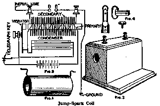
Illustration: Jump-Spark Coil
After the core wires are bundled, the core is wrapped with one or two layers of manila paper. The straighter the wire the more iron will enter into the construction of the core, which is desirable. Beginning half an inch from one end, No. 16 cotton-covered magnet wire is wound from one end to the other evenly and then returned, making two layers, and the terminals tied down to the core with twine. Core and primary are then immersed in boiling paraffine wax to which a small quantity of resin and beeswax has been added. This same wax may be used later in sealing the completed coil into a box. Over this primary is now wrapped one layer of okonite tape, or same thickness of heavily shellacked muslin. This completed primary will now allow of slipping into the hole in the secondary.
Should the secondary have been purchased without a case, a wooden box of mahogany or oak is made, large enough to contain the secondary and with an inch to spare all around, with room also for a small condenser; but if it is not convenient to do this work, a box like that shown in Fig. 2 may be purchased at a small cost. A 7/8-in. hole is bored in the center of one end, through which the primary core projects 1/8 in. This core is to be used to attract magnetically the iron head of a vibrating interrupter, which is an important factor of the coil. This interrupter is shaped as in Fig. 4, and is fastened to the box in such a way that the vibrator hammer plays in front of the core and also that soldered connections may be made inside the box with the screws used in affixing the vibrator parts to the box. The condenser is made of four strips of thin paper, 2 yd. long and 5 in. wide, and a sufficient quantity of tinfoil. When cut and laid in one continuous length, each piece of tin-foil must overlap the adjoining piece a half inch, so as to form a continuous electrical circuit. In shaping the condenser, one piece of the paper is laid down, then the strip of tin-foil, then two strips of paper and another layer of foil, and finally the fourth strip of paper. This makes a condenser which may be folded, beginning at one end and bending about 6 in. at a time. The condenser is next wrapped securely with bands of paper or tape, and boiled in pure paraffine wax for one hour, after which it is pressed under considerable weight until firm and hard. One of the sheets of tin-foil is to form one pole of the condenser, and the other sheet, which is insulated from the first, forms the other pole or terminal. (This condenser material is purchasable in long strips, ready for assembling.)
The wiring diagram, Fig. 3, shows how the connections are made. This method of connecting is suitable for all coils up to 1-1/2 in. spark, but for larger coil better results will be obtained by using an independent type of interrupter, in which a separate magnet is used to interrupt the circuit. Besides the magnetic vibrators there are several other types, such as the mercury dash-pot and rotary-commutator types, but these will become better known to the amateur as he proceeds in his work and becomes more experienced in coil operation.
Continue to:
More:
- A Postcard Rack
- How To Make Lantern Slides
- The Fuming Of Oak
- How To Give An Electric Shock While Shaking Hands
- Gear For Model Work
- II - How to Make a Mold
My Books

