The Direct Optical Projection Of Electro-Dynamic Lines Of Force And Other Electro-Dynamic Phenomena
Description
This section is from "Scientific American Supplement". Also available from Amazon: Scientific American Reference Book.
The Direct Optical Projection Of Electro-Dynamic Lines Of Force And Other Electro-Dynamic Phenomena
By Prof. J.W. MOORE.
II. Loops
If the wire, with its lines of force, be bent into the form of a vertical circle 1⅛ in. in diameter, and fixed in a glass plate, some of the lines of force will be seen parallel to the axis of the circle. If the loop is horizontal, the lines become points.

Fig. 14.

Fig. 14a.
Fields Of Loops And Magnets
Place now a vertical loop opposite to the pole of a short bar magnet cemented to the glass plate with the N pole facing it. If the current passes in one direction the field will be as represented by Fig. 14b; if it is reversed by the commutator, Fig. 14c is an image of the spectrum. Applying Faraday's second principle, it appears that attraction results in the first case, and repulsion in the second. The usual method of stating the fact is, that if you face the loop and the current circulates from left over to right, the N end of the needle will be drawn into the loop.

Fig. 14b.

Fig. 14c.
It thus becomes evident that the loop is equivalent to a flat steel plate, one surface of which is N and the other S. Facing the loop if the current is right handed, the S side is toward you.
To Show The Actual Attraction And Repulsion Of A Magnet By A "Magnetic Shell."
Produce the field as before (Fig. 14), carry a suspended magnetic needle over the field. It will tend to place itself parallel to the lines of force, with the N pole in such a position that, if the current passes clockwise as you look upon the plane of the loop, it will be drawn into the loop. Reversing the position of the needle or of current will show repulsion.
Clerk Maxwell's method of stating the fact is that "every portion of the circuit is acted on by a force urging it across the lines of magnetic induction, so as to include a greater number of these lines within the embrace of the circuit."2
If the horizontal loop is used (Fig. 14a), the needle tries to assume a vertical position, with the N or S end down, according to the direction of the current.
If it is desired to show that if the magnet is fixed and the loop free, the loop will be attracted or repelled, a special support is needed.
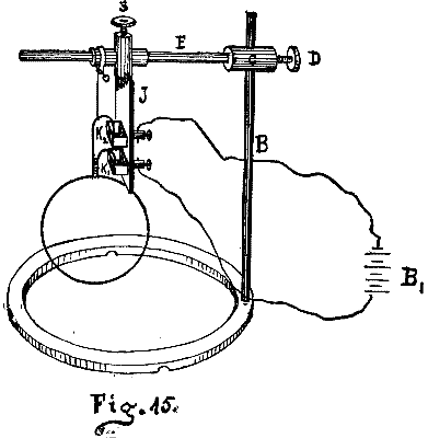
Fig. 15
A strip (Fig. 15) of brass, J, having two iron mercury cups, K K, screwed near the ends, one insulated from the strip, is fastened upon the horizontal arm of the ring support, Fig. 9, already described. The cups may be given a slight vertical motion for accurate adjustment. Small conductors (Figs. 16, 17, 18), which are circles, rectangles, solenoids, etc., may be suspended from the top of the plate by unspun silk, with the ends dipping into the mercury. The apparatus is therefore an Ampere's stand, with the weight of the movable circuit supported by silk and with means of adjusting the contacts. The rectangles or circles are about two inches in their extreme dimension. Horizontal and vertical astatic system are also used - Figs. 18, 18a. The apparatus may be used with either the horizontal or vertical lantern.

Fig. 16. Fig. 17.

Fig. 18. Fig. 18a.
If the rectangle or circle is suspended and a magnet brought near it when the current passes, the loop will be attracted or repelled, as the law requires. The experiments usually performed with De la Rive's floating battery may be exhibited.
The great similarity between the loop and the magnet may be shown by comparing the fields above (Figs. 14b, 14c) with the actual fields of two bar magnets, Figs. 19, 19a.
It will be noticed that the lines in Fig. 19, where unlike poles are opposite, are gathered together as in Fig. 14b, - where the N end of the magnet faces the S side of the magnetic shell; and that in 19a, where two norths face, the line of repulsion has the same general character as in 14c, in which the N end of the magnet faces the N side of the shell.
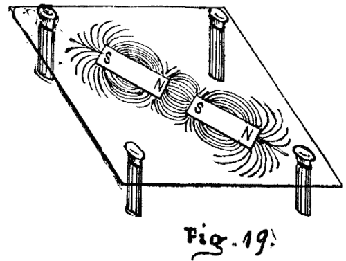
Fig. 19.

Fig. 19a.
Instead of placing the magnet perpendicular to the plane of the loop, it may be placed parallel to its plane. Fig. 14d shows the magnet and loop both vertical.
The field shows that the magnet will be rotated, and will finally take for stable equilibrium an axial position, with the N end pointing as determined by the rule already given.
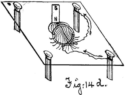
Fig. 14d.
If two loops are placed with their axes in the same straight line as follows, Figs. 14f, 14g, a reproduction of Figs. 14b and 14c will become evident.
It is obvious from these spectra that the two loops attract or repel each other according to the direction of the current, which fact may be shown by bringing a loop near to another loop suspended from the ring stand, Fig. 9, or by using the ordinary apparatus for that purpose - De la Rive's battery and Ampere's stand.
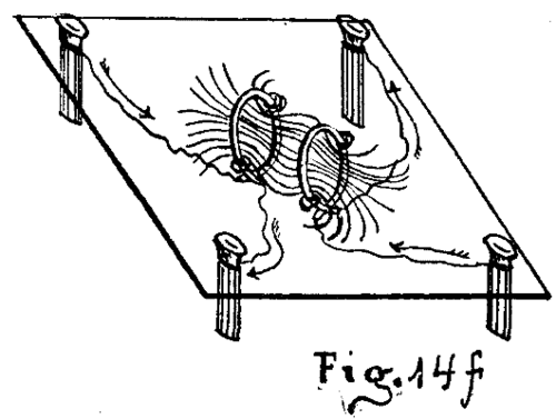
Fig. 14f.
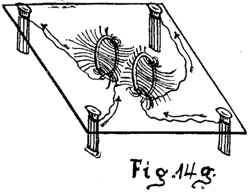
Fig. 14g.
If two loops are placed in the same vertical plane, as in Figs. 14h and 14i, there will be attraction or repulsion, according to the direction of the adjacent currents. The fields become the same as Figs. 8 and 8a, as may be seen by comparing them with those figures.
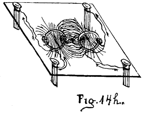
Fig. 14h.
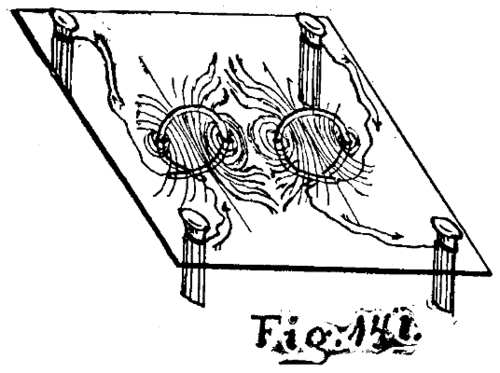
Fig. 14i.
Having thus demonstrated the practical identity of a loop and a magnet, we proceed to examine the effects produced by loops on straight wires.
If the loop is placed with a straight wire in its plane along one edge, there will be attraction or repulsion, according to the direction of the two currents, Figs. 20 and 20a, which are obviously the same as Figs. 8 and 8a.
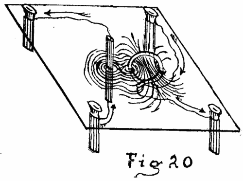
Fig. 20.

Fig. 20a.

Fig. 20b.

Fig. 20c.
If the wire is placed parallel to the plane of the loop and to one side, Figs. 20b and 20c, there will be rotation (same as Figs. 4b and 4c).
If the loop is horizontal and the wire vertical and on one side, the Figs. 20d, 20e are the same as 4d and 4e.
If the loop is horizontal and the wire vertical and axial, 20f and 20g, there will be rotation, and the figures are mere duplicates of 4g and 4h.

Fig. 20d.

Fig. 20e.
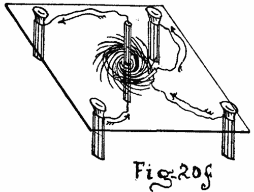
Fig. 20f.
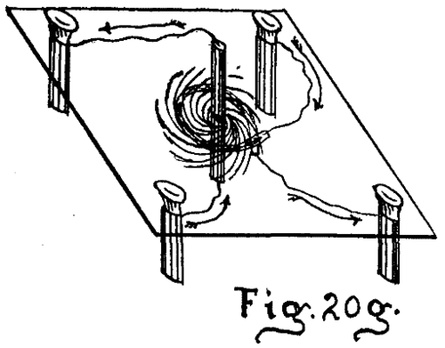
Fig. 20g.
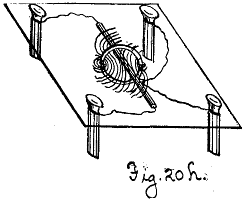
Fig. 20h.
Fig. 20h shows a view of 20f when the wire is horizontal and the plane of the loop vertical. It is like 4i.
To verify these facts, suspend a loop from Ampere's stand, Fig. 9, and bring a straight wire near.
A small rectangle or circle may be hung in a similar manner. When the circuit is closed, it tends to place itself with its axis in a N and S direction through the earth's influence. The supposition of an E and W horizontal earth current will explain this action.
To exemplify rotation of a vertical wire by a horizontal loop, Fig. 21 may be shown.
A circular copper vessel with a glass bottom (Fig. 21) has wound around its rim several turns of insulated wire. In the center of the vessel is a metallic upright upon the top of which is balanced in a mercury cup a light copper [inverted U] shaped strip. The ends of the inverted U dip into the dilute sulphuric acid contained in the circular vessel.
The current passes from, the battery, up the pillar, down the legs of the U to the liquid, thence through the insulated wire back to the battery.
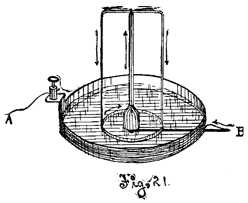
Fig. 21.
This is the usual form of apparatus, modified in size for the vertical or horizontal lantern.
(To be continued.)
[1]
An expansion of two papers read before the A.A.A.S. at the Ann Arbor meeting.
[2]
Electricity and Magnetism, Maxwell, p. 137, §§ 489, 490.
Continue to:
My Books

