Spindle Bearings, Back Gears, Triple Gear Mechanism. Part 6
Description
This section is from the book "Lathe Design, Construction And Operation, With Practical Examples Of The Lathe Work", by Oscar E. Perrigo. Also available from Amazon: Lathe Design: Construction And Operation.
Spindle Bearings, Back Gears, Triple Gear Mechanism. Part 6
In this lathe a four-step cone is used, therefore giving only eight speeds. The lathe is a small one, the swing being 14 inches and intended for light work and a comparatively fast range of speeds. It will be noticed that the countershaft cone is considerably larger than the spindle cone, which is an unusual condition.
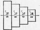


Fig. 88. - Back Geared Lathe, 8 speeds.

Fig. 89. - Back Geared Lathe, 10 speeds.
In the next example a lathe having a five-step cone is selected. It is a 19-inch swing lathe and intended for much heavier work and back gears having a much wider face, in fact 50 per cent, while the pitch of the teeth is in about the same proportion.
Figure 89 shows the driving mechanism for this lathe, whose back gear ratio is 13.46 to 1, and whose countershaft speed is 130 revolutions per minute.
In this case the increase of speed between the fastest back gear speed and the slowest cone speed is 23.7, while the next speed below varies only 10 revolutions, which is a palpable fault in the caclulation of the speed progression. The following are the spindle speeds:
Cone Speeds. | 343.0 |
206.0 | |
130.0 | |
82.2 | |
49.2 |
Back Gear Speeds | 25.50 |
15.30 | |
9.65 | |
6.10 | |
3.65 |
For this size of lathe the highest and lowest speeds are as they should be, but the proper progression is at fault.
Figure 90 is a diagram from a lathe of 17-inch swing and having a five-step cone, a back-gear ratio of 12 to 1, and a countershaft speed of 150 revolutions per minute. The same fault of too great a difference between the fastest back gear speed and the slowest cone speed is observed.
The spindle speeds are as follows:
Cone Speeds | 371.0 |
231.0 | |
150.0 | |
97.5 | |
60.6 |
Back Gear Speeds | 30.90 |
19.25 | |
12.50 | |
8.10 | |
5.05 |
The difference above referred to is 29.7, while the next difference below is only 11.35.
The next example is of a 30-inch swing, triple geared lathe in which the speed calculations show an error only too common among lathes of this type. It will be noticed by reference to the engraving, Fig 91, that the countershaft cone is considerably larger than the spindle cone, which is entirely unnecessary since the same object might have been secured by running the countershaft faster and the parts need not be so heavy or expensive. The questions of proportion and progression of speeds can be easily taken care of when both cones are alike, if the proper calculations are made.
The countershaft speed is 110 revolutions per minute.
The back gear ratio is 15.23 and the triple gear ratio 57.74 to 1. The spindle speeds are given below:
Cone Speeds | 372.0 |
212.0 | |
137.0 | |
88.7 | |
52.5 |
Back Gear Speeds | 24.40 |
13.90 | |
9.00 | |
5.82 | |
3.45 |
Triple Gear Speeds | 6.44 |
3.67 | |
2.37 | |
1.53 | |
.81 |
By reference to these figures it will be seen that the triple gear speed of 6.44 exceeds both the back gear speeds of 3.45 and 5.82, which renders them comparatively useless, or which makes the two higher speeds given by the triple gears of no effect in practical work. Otherwise, of the five triple gear speeds two are of no practical use.
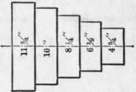


Fig. 90. - Back Geared Lathe, 10 speeds.
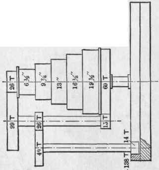
Fig. 91. - Triple Geared Lathe, 15 speeds.
Hence, we have a lathe provided with fifteen nominal speeds, which really has but thirteen. This point will be more readily appreciated by referring to the speed curve shown in the diagram, Fig. 92, and the faults of designing more clearly brought out by comparing this diagram with the two curves shown in the diagram given in Fig. 87, being careful to note that the upper curve representing the triple gear speeds is drawn to a scale ten times larger than the curve for the back gear speeds and the cone speeds. The object of this was to show more clearly the progressive increase of the triple gear speeds, whose continued upward tendency would properly join with those of the back gear if the latter were drawn to the same scale, which the dimensions of the page would not admit. The figures for these speeds are given on a previous page, to which the reader is referred, and a comparison with the speeds given in the last example is suggested.
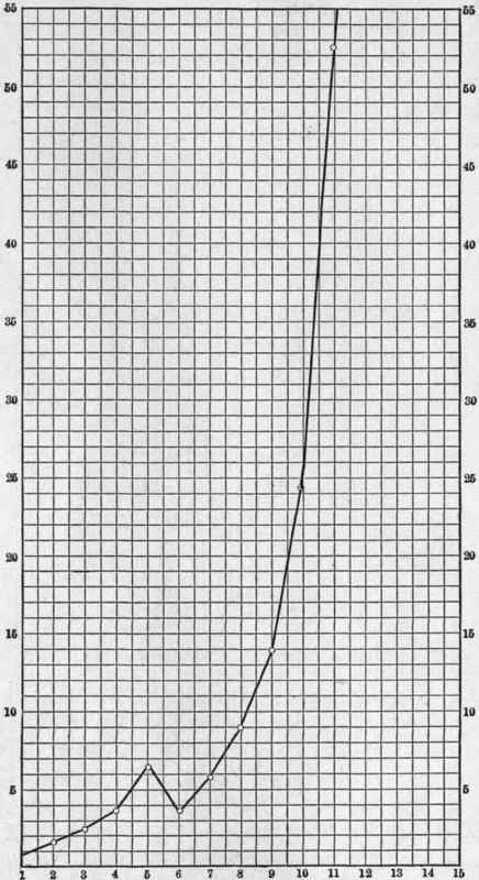
Fig. 92. - Speed Curve of a Triple Geared Lathe Wrongly Designed.

Fig. 93. - Triple Gearing of a Lodge & Shipley Lathe.
In the diagrams of driving mechanisms in Figs. 85,86,88,89, 90, and 91, the countershaft cone is shown above the spindle cone and the back gear and triple gear mechanisms below. This is so arranged for convenience in giving the relative dimensions and proportions of the parts. While it is the usual method to place the back gear device at the back of the lathe head-stock or in the rear of the spindle, it is not at all necessary that it should be so placed, and in fact, on some of the larger lathes, it is placed in front of the main spindle as a matter of convenience.
The essential parts of the triple gear mechanism in connection with the usual back gears are well represented in the rear view of a head-stock shown in Fig. 93, in which the triple gear device is shown engaged and the quill pinion thrown out of engagement with the face gear. In this case a clutch connection between the back gear shaft and the triple gear shaft serves to handle the pinions on both so as to be moved into and out of engagement at one and the same time, thereby running the lathe as a back geared or a triple geared lathe, by a very simple and convenient change. The design is of a lathe built by Lodge & Shipley.
Continue to:
My Books

