Wood Turning. Part 2
Description
This section is from the book "Wood Turning", by George Alexander Ross. Also available from Amazon: Wood Turning.
Wood Turning. Part 2
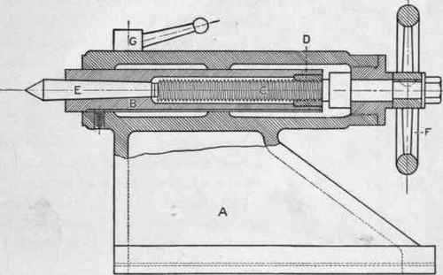
Fig. 8.
The hand wheel F is used to turn the screw in the spindle; the clamp G is used to fasten the spindle in place when once set.
On the side of the spindle is a slot (not shown in the figure) into which the end of a pin or screw projects, to provide against the spindle's turning when it is drawn in or out of the tail stock.
The tool rest. The tool rest (Fig. 9) is also made up of several pieces. Its function is to provide a rest for tools when the operator is at work. The parts are the bed plate A, the tee-socket B, the clamp C, and the rest D. The manner in which the rest is fastened to the bed differs in different makes of lathes; in some it is fastened by a clamp, sometimes on the side and sometimes underneath; in others, by a hand wheel.
The bed or shears. The bed is the main casting on which the head stock, tail stock, and rest are fastened. The bed is sometimes made of wood instead of iron. The legs are the supports on which the bed is fastened.
The countershaft. The countershaft is that part of the driving mechanism which is placed directly over the lathe. It is usually fastened to the ceiling.
The parts of the countershaft are the hangers, the tight and loose pulleys, the cone pulley, the shaft, the shifter rod, and the shifter, the end of which hangs down within easy reach of the operator (see Fig. 5).
The line shaft. The line shaft is the main driving shaft, and may be some distance from the lathe (see Fig. 5).
The belting. The driving of the lathe is accomplished by means of belts, or bands of leather, arranged in the following manner: The line shaft is driven from an electric motor or from a steam engine direct, and may turn at the rate of 150 to 400 revolutions per minute. (It has been determined by experiment that for wood turning, a speed of 300 revolutions is most satisfactory.) From a pulley on the line shaft a belt runs to the loose pulley on the countershaft. From the cone pulley on the countershaft a belt runs to the cone pulley on the lathe,
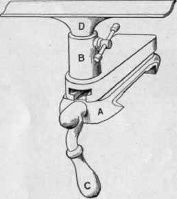
Fig. 9.
When it is desired to have the cone pulley on the lathe revolve, the shifter is moved to one side. This movement throws the belt over on to the tight pulley on the countershaft, and this, in turn, causes the cone pulley on the lathe to revolve.
The gearing of the lathe. By this term is meant the speed at which the lathe is belted to give the desired number of revolutions per minute. It will be observed from Fig. 5 how this is accomplished. On the line shaft is a pulley larger than that on which the belt runs on the countershaft. This means that the countershaft makes a greater number of revolutions than the line shaft, or, in other words, the number of revolutions is increased by the belt running from a large pulley to a smaller one.
The rules for obtaining the diameters and speeds of pulleys are as follows.
1. The diameter and number of revolutions of the driver and diameter of the driven being given to find its number of revolutions: Multiply the diameter of the driver by the number of its revolutions, and divide the product by the diameter of the driven; the quotient will be the number of revolutions of the driven.
2. The diameter and revolutions of the driver being given, to find the diameter of the driven that shall make any given number of revolutions in the same time: Multiply the diameter of the driver by its number of revolutions, and divide the product by the number of revolutions of the driven; the quotient will be its diameter.
3. To ascertain the size of the driver: Multiply the diameter of the driven by the number of revolutions you wish it to make, and divide the product by the revolutions of the driver; the quotient will be the diameter of the driver.
The face of a pulley for a nonshifting belt should be round or crowning, and for a shifting belt, straight. (In ordering pulleys the exact size of the shaft on which they are to go should be given.)
Motor head and gap lathes. Before passing to tools and materials we may mention the motor head and gap lathes, - lathes that have appeared on the market during the past few years.
The improvements shown in the speed lathe as compared with primitive types have been succeeded by a self-contained lathe known as a motor-head lathe. This type of lathe eliminates all overhead transmission and belts, thus giving to a shop a more pleasing appearance than belt-driven machines; also giving more light, less dust, and no danger from breaking belts or countershafts.
The lathes here shown are the product of the Oliver Machinery Company of Grand Rapids, Michigan, and selected because they are the ones with which the writer is most familiar.
In Fig. 9 A is shown a lathe, to drive which a belt is used.
Another feature of this machine is the overhanging spindle, which is used for large face-plate work. The lathes that follow are the latest designs of this type of machine.

Fig. 9 A.
It will be observed from Fig. 10 that the lathe is practically the same in all its features as the ordinary belted speed lathe, with the exception of the head stock or motor head, the motor taking the place of the cone pulley and overhead mechanism.
This type of lathe is so arranged that fifteen different speeds are obtained; this makes it a desirable machine in many ways. The starting box and switch fastened on the left-hand end of the bed are within easy reach of the operator, thus making control of the machine a simple matter.

Fig. 10.
An improvement on the above lathe is shown in Fig. 11, a hand feed and compound swivel rest being features that are of great help in the production of certain kinds of work, especially in a pattern shop or brass-turning room.
Continue to:
My Books

