The Halved Joint. Continued
Description
This section is from the book "Woodwork Joints", by William Fairham. Also available from Amazon: Woodwork joints.
The Halved Joint. Continued
The joint lettered B in Fig. 28 is a "Cross Halving Joint" where each piece runs through the other. Fig. 39 shows this joint separated, and Fig. 40 shows a similar joint separated where the joint is made edgeways.

Fig. 39. - Cross Halving Joint.

Fig. 40. - Cross Halving Joint Edgeways.
 Fig. 41. - Tee Halving Joint.
Fig. 41 shows a "Tee Halving Joint" with a dovetail cut on the edge. This is seldom used except as a woodwork exercise.
Fig. 42 is a "Dovetailed Halving Joint" used for lengthening timber, and is also a favourite Manual Training model. It might also come under the heading of scarf joint, although rarely used in actual practice as such. As a practical woodwork exercise it calls for accurate marking out and careful fitting.
 Fig. 42. - Dovetailed Halving Joint used for Lengthening Timber.

Fig. 43. - Dovetailed and Halved Joint.

Fig. 44. - Dovetailed Halved Joint with Shoulders.
Fig. 43 shows a combination of a halved joint dovetailed edgeways, whilst Fig. 44 shows a dovetailedhalved joint with the shoulders housed. This latter is seldom used in actual work.
At Fig. 45 we have the application of halving joints when constructing a barrow wheel. The centre portion is an example of three pieces half-lapped or, as it is sometimes called, one-third lapped. A sketch of the three pieces separated is shown at L, B, C, Fig. 46 .
This joint is extensively used in the pattern making trade for lap-jointing the arms of pulley patterns, etc. It is probably the most difficult of the halving joints to mark out and construct with the desired degree of accuracy.
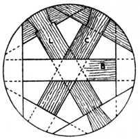
Fig. 45. - Halved Joints on Barrow Wheels.

Fig. 46. - Detail of Halved Joints in Fig. 45 .
Fig. 47 shows a combination of a bevelled dovetail half-lapped joint. This is only used as a puzzle joint. When neatly constructed and glued together it is apparently impossible to make it, showing as it does a half lap on one side and a dovetailed half lap on the reverse side.
Fig. 48 is the end view of a kitchen table with drop leaf, showing the skirting board scribed to the solid side. A table of this type is fastened to the wall with two iron holdfasts which engage the ends of the table.
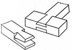
Fig. 47. - Bevelled Dovetailed Half Lap.

Fig. 48. - Bracket of Drop Table.
 Figs. 49 and 50. - Separate pieces of Halved Moulded Joint.
 Fig. 51. - Oblique Cross Halving Joint.
The hinged bracket frame shows the application of the halving joint to bracket supports for this and similar purposes, such as brackets to support shelving, etc. In this example the hinged brackets turn underneath the table top, and allow the leaf to drop out of the way when not required. The dotted lines show the position of a shelf for boots and shoes.

Fig. 52. - Manual Training Halved Exercise Joint.

Fig. 53. - Exercise Dovetail Joint.
 Fig. 54. - Carpentry Tie Joint.
Figs. 49 and 50indicate the halving of cross pieces which have their edges moulded; the pieces are shown separately, the moulding being omitted to give a clearer representation of the method of construction.
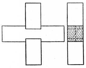
Fig. 55. - Cross Halving Joint with Housed Corners.

Fig. 56. - The parts of Fig. 55 shown separate.
Fig. 51 is an "Oblique Cross Halving Joint" where the two pieces are not at right angles. A plan and elevation of the joint are shown at the left, whilst a sketch of one piece of the joint is given in the right-hand illustration.
Figs. 52 and 53are principally used as Manual Training models, and call for patience and manual dexterity.
Fig. 54 is used in carpentry and joinery where a tie or cross piece ties joists or beams at an angle.
Fig. 55 shows the elevation and end view of a "Cross Halving Joint" with housed or notched shoulders. This joint is seldom used in actual practice. The separate parts are given in Fig. 56 .
At Fig. 57 are shown two cross rails and an upright halved together. This type of joint is used where threepieces meet, as is the case in building the framing of a poultry house. The joint is nailed together.

Fig. 57. - Cross Rail and Upright Halved Joint.

Fig. 58. - Workshop Trestle Joint.
 Fig. 59. - Cellarette Partition Joints.
Fig. 58 is the end view of an ordinary workshop trestle, showing the application of dovetailed halvingwhere the legs have a tendency to strain outwards. The inset sketch of joint shows the housing of the top rail to receive the legs.
Fig. 59 shows a deep drawer, generally known as a cellarette, and used in a sideboard to accommodate wine bottles. Here we have a good example of halving the cross pieces so as to form compartments. The part shown separately illustrates the method of construction. The ends of these pieces engage the housings or grooves of the drawer sides. Pigeon holes or compartments in stationery cases, bookcases and writing bureaux are constructed in a similar manner, although the method of housing, or combined halving and housing, is to be preferred in some cases.
 Fig. 60. - Joint used for Table with Circular Top or Rim.
At Fig. 60 is the plan of a circular table having a small circular shelf with the top removed. The rims orframing are built by the method known as laminating (see Fig. 23 in chapter on the The Glued Joint), after which they are veneered on the face sides. The applicationof the halving joint to the shaped bottom rails, which in this case carry and support the small shelf, is shown in the part elevation.
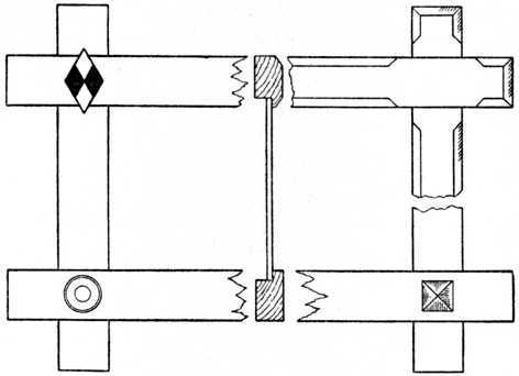 Fig. 61 (A). - Oxford Frame with Halved Joints. (Four alternative corner treatments are given.)

Fig. 61 (B). - Halved Joint of Oxford Frame with front edges champered.
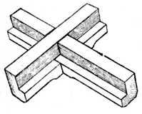
Fig. 61 (C). - Back view of Oxford Frame.
Fig. 61 (A)shows the well-known "Oxford frame," illustrating halved joints when the edge is rebated. Figs. 61 (B) and 61 (C)make clear the construction of this type of joint. Alternative suggestions are shown for the treatment of the corners, the simple inlay being black and white (ebony and holly or boxwood). Frames of this type are made in various widths and sizes and are used for pictures, mirrors, etc.
The tools used for making joints of the above class are: planes, the gauge, tenon or other saw, chisels, try square, and in some cases a joiner's bevel to obtain and mark the necessary angles, pencil and marking knife.
Plane up the face side and face edge of the timber, gauge and plane to both thickness and width; mark shoulders with pencil or marking knife; gauge to the thickness of the required halving; saw waste portions away; pare up with chisel to a good fit; glue or glue and screw, or use paint as previously mentioned, and then level off the surfaces.
Continue to:
My Books

