Pyrometer
Description
This section is from "The American Cyclopaedia", by George Ripley And Charles A. Dana. Also available from Amazon: The New American Cyclopædia. 16 volumes complete..
Pyrometer
Pyrometer (Gr.![]() , fire, and
, fire, and![]() , measure), any instrument for determining degrees of heat higher than those which can be measured by ordinary thermometers. Pyrometers are required in the determination of the intensity of the heat of furnaces, and in ascertaining at what temperatures metals melt and chemical compounds are formed or are decomposed. They may be arranged, according to the principles on which they act, in the following classes: 1, pyrometers using the expansion of solids as a means of measuring high temperatures, of which class Darnell's is a type; 2, those using the contraction of baked clay, as Wedgwood's; 3, those employing the expansion of air, as Pouillet's, Regnault's, and Jolly's; 4, those using the known melting points of solids; 5, those depending on the chemical decomposition of solids, as Lamy's; 6, those measuring temperatures by heating a known weight of water, by allowing to cool in it a known weight of platinum or other metal, which has been heated to the temperature of the space or of the body to be tested, as Pouillet's; 7, those which determine temperatures from the measures of the strength of thermo-electric currents produced by heating the junction of two different metals, as Bec-querel's; 8, those which determine temperatures by the measurement of changes, produced by heat, in the electrical resistance of a length of platinum wire, as Siemens's; 9, those which use the expansion of the wave length of a sound, which traverses a tube placed in the furnace whose temperature is to be measured, as Mayer's. "We will restrict our detailed description to the three pyrometers which experience has shown to be most trustworthy, viz.: Daniell's pyrometer, the air pyrometer, and Siemens's pyrometer.
, measure), any instrument for determining degrees of heat higher than those which can be measured by ordinary thermometers. Pyrometers are required in the determination of the intensity of the heat of furnaces, and in ascertaining at what temperatures metals melt and chemical compounds are formed or are decomposed. They may be arranged, according to the principles on which they act, in the following classes: 1, pyrometers using the expansion of solids as a means of measuring high temperatures, of which class Darnell's is a type; 2, those using the contraction of baked clay, as Wedgwood's; 3, those employing the expansion of air, as Pouillet's, Regnault's, and Jolly's; 4, those using the known melting points of solids; 5, those depending on the chemical decomposition of solids, as Lamy's; 6, those measuring temperatures by heating a known weight of water, by allowing to cool in it a known weight of platinum or other metal, which has been heated to the temperature of the space or of the body to be tested, as Pouillet's; 7, those which determine temperatures from the measures of the strength of thermo-electric currents produced by heating the junction of two different metals, as Bec-querel's; 8, those which determine temperatures by the measurement of changes, produced by heat, in the electrical resistance of a length of platinum wire, as Siemens's; 9, those which use the expansion of the wave length of a sound, which traverses a tube placed in the furnace whose temperature is to be measured, as Mayer's. "We will restrict our detailed description to the three pyrometers which experience has shown to be most trustworthy, viz.: Daniell's pyrometer, the air pyrometer, and Siemens's pyrometer.
Of the others we will give only general descriptions of the principles on which they depend. 1. The first pyrometer based on the expansion of solids appears to have been invented by Musschenbroek about 1730. This instrument, which he called a "pyrometer," was formed of a metallic bar, fixed at one end, and connected at the other with wheel work which multiplied the motion of elongation caused by the elevation of its temperature. This was improved by others, who directed their efforts principally to the mechanism by which the motion was communicated to the index. Many of these contrivances are described in the article " Thermometer and Pyrometer " in vol. ii. of the " Natural Philosophy" published in the "Library of Useful Knowledge " (London, 1832). Daniell's pyrometer, called by its inventor "the register pyrometer," was first described in the "Transactions of the Royal Society " for 1830. It consists of two parts, the register, fig. 1, and the scale, fig. 2. The register is a solid bar of black-lead earthenware, A, highly baked. In the axis of this a hole is drilled, reaching from one end of the bar to within half an inch of the other extremity. In this cylindrical cavity is placed a rod of platinum or of iron, a a, 6 1/2 in. long.
Upon the top of the bar rests a cylindrical piece of porcelain, c c, long enough to project a short distance beyond the extremity of the black-lead bar, to serve as an index. It is confined in its position by a ring or strap of platinum, d, passing round the top of the black-lead tube, which is partly cut away at the top; the ring is tightened by a wedge of porcelain, e. When it is exposed to a high temperature, the expansion of the metallic rod, a a, forces the index forward to a distance equal to the difference in the amount of expansion between the metallic rod and the black-lead bar, and when cool it will remain protruded to the same distance, which will be greater or less according to the temperature; the exact measurement of this distance is effected by the scale, fig. 2. This scale is independent of the register, and consists of two rules of brass, f g, joined together by their edges accurately at a right angle, and fitting square upon the two sides of the black-lead bar. Near one end of this double rule a small brass plate, h, projects at a right angle, which when the instrument is used is brought down upon the shoulder of the register, formed by the notch cut away for the platinum strap.
To the extremity of the rule nearest this brass plate is attached a movable arm, D, turning at its fixed extremity upon a centre, i, and at the other end carrying an arc of a circle, E, the radius of which is exactly 5 in., accurately divided into degrees and thirds of a degree. Upon this arm, at the centre, k, another lighter arm, C, is made to turn, carrying upon the extremity of its longer limb a vernier, H, which moves on the face of the arc, and subdivides the graduation into minutes. The shorter arm, which is half an inch in length, crosses the centre, and terminates in an obtuse steel point, m, turned inward at a right angle. To use the instrument, the metallic rod is placed in the register, and the index is pressed firmly down upon its extremity and secured tightly by the platinum strap and the wedge. The position of the index is then read off on the scale, by placing the register in the reentering angle for its reception, with the cross piece firmly held against the shoulder, and the steel point, m, resting on the top of the index, in a notch cut for it, which coincides with the axis of the rod. A similar observation, made after the instrument has been heated and allowed to cool, gives the value of the expansion.
The scale of the pyrometer is compared with that of the mercurial thermometer, by observing the amount of expansion between two fixed points, such as the melting of ice and the boiling of mercury. In this pyrometer the temperature to which its register has been exposed is deduced from the amount of elongation of its metallic bar, on the supposition that the amount of elongation for an elevation of the same number of degrees is the same whether these degrees occur in the lower or in the highest regions of the thermometric scale. We now know, however, that the coefficient of expansion of a solid is not constant throughout the range of available temperatures; hence, to obtain accurate measures with Daniell's pyrometer, it should be graduated by noting its indications at successive high temperatures, the ther-mometric values of which have been determined with an air thermometer. We should also be sure that successive heatings and coolings of the metallic bar do not change its coefficient of expansion. 2. Wedgwood's pyrometer, using the contraction of baked clay as a measure, consists of a metallic groove or gauge, the sides of which gradually converge; pieces of very pure clay are made into small cylinders, having one side flattened, and, being heated to redness, made just to fit the larger extremity of the groove.
It is a property of clay permanently to contract and become harder by exposure to a high temperature, in consequence of its losing a portion of the water with which it is combined; and it was supposed that the amount of the contraction was exactly proportioned to the intensity of the heat to which it is exposed. The amount of contraction in the clay cylinders, after being exposed to the temperature which it was desired to measure, was easily determined by allowing the cylinders to slide from the top of the groove downward, till they arrived at a point beyond which they would not pass. Mr. Wedgwood divided the whole length of this gauge into 240 parts or degrees, each of which he calculated to be equal to 130° of Fahrenheit's scale; and the zero of his scale, indicating a red heat, corresponded, according to his experiments, to 1,077°. The difficulty of obtaining clay of uniform composition is of itself an almost insuperable objection to this method of estimating high temperatures; and it has been since ascertained that the observation upon which it is founded is not correct, for clay will contract as much by the long continuance of a comparatively low heat as by a short continuance of a high one.
Hence the degrees of heat which Wedgwood's pyrometer has been applied to measure have been enormously exaggerated. Thus, Daniell's pyrometer shows that the melting point of cast iron is 2,786°, and the highest temperature of a good wind furnace about 3,300°; points which were estimated by Wedgwood at 20,577° and 32,277° respectively. In other words, Wedgwood's pyrometer gave figures nearly ten times higher than those obtained by Daniell's. 3. The expansion of air is used in pyrometers contrived by Pouillet, Regnault, and Jolly. If thermometers carefully made of any number of solids and liquids are all simultaneously exposed to the same successive elevations of temperature, it will be found that no two of them agree in their readings throughout the range of temperatures; but if we at the same time expose a set of thermometers made of the permanent gases (i. e., of gases which have never been liquefied by pressure and cold), as oxygen, nitrogen, air, hydrogen, and carbonic oxide, we will find that they all agree in their readings.
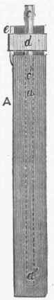
Fig. 1. - Daniell's Pyrometer, Register.

Fig. 2. - Daniell's Pyrometer, Scale.
For this reason, if for no other, these permanent gases should have the preference as bodies to form the expanding material of thermometers; but the theory of the thermodynamics of gases shows that from the expansion of these gases alone can we arrive at the knowledge of true temperatures. In short, it appears that while the coefficients of expansion of solids and liquids increase with the temperature, the permanent gases have the same coefficient of expansion, which also remains constant throughout the range of available temperatures. Indeed, men of science have agreed that the determination of temperature rests upon the assumption that the permanent, or, as they are now called, perfect gases, when subjected to a constant pressure, expand proportionately to the rise of temperature. This expansion, in the case of dry air, amounts for each degree centigrade to 0.003665, or 1/273 of the volume at 0° C.; or what is the same, the pressure of a mass of air kept at a constant volume increases 0.003665 of its pressure at 0° C. for each rise of 1° C. in temperature. The simplest air thermometer, and the one best adapted to practical purposes, is that of Jolly. Its action depends on the law just given.
A hollow globe of hard porcelain (platinum cannot be used by reason of its permeability to gases at high temperatures), A, fig. 3, communicates through the capillary tube E with the fixed vertical glass tube B. The tube B communicates with the open glass tube C through the rubber tube D. The tubes B and C and the connecting rubber tube contain mercury. The tube C moves upward and downward in a vertical direction, and carries with it the rubber tube D, and thus the surface of the mercury in B can always be brought to coincide with a mark, R, on the capillary tube E; so that the air in A and E is always observed under a constant volume after it has been heated to any temperature. The height of the mercury in C above R is read off on scales formed by cutting lines in the silvering of slips of glass mirrors placed behind the tubes C and R. When the centre of the pupil of the eye is seen in the plane passing through the surface of the mercury, we know that the line of sight is perpendicular to the length of the columns of mercury, and that their true difference of levels has been correctly determined.
To graduate the apparatus, the globe is surrounded with melting ice and the mercury is brought to the level R in the tube E; then the height of the barometer, b0, and the height, h0, of the mercury in C above the level R in E, are observed. We will call b0+h0=H0. The heights b0 and h0 must be reduced to what they would be if the mercury in the apparatus were at 0° C. To measure any temperature, t, we expose the globe to this temperature for a length of time sufficient to heat uniformly the contained air, which is known to be the case when the mercury is stationary in B and in C. When this condition has been reached we obtain the height h, which is the difference of the readings of the levels of mercury at R and in C reduced to 0° C., and then read the height b of the barometer reduced to 0° C. Calling h+b=H, we have for the sought temperature t = (H+H0)/(.003665.H0-3c H), in which formula 3C is the cubical expansion of the porcelain or other material forming the globe. In this formula the volume of air contained in the capillary tube E, up to the mark R, is neglected; but when the most accurate determinations are desired, it must be remembered that this portion of air in the pyrometer remains at or about the temperature of the air surrounding the part of the apparatus outside of the furnace.
This temperature, which we will call t', can be determined by means of a thermometer placed close to the tube E. Now to obtain the exact value of the temperature to which the globe has been exposed, we must add to the value of t as given above the following correction: t.ύ/υ.H/H0. 1/(1+.003665t)' in which expression v represents the volume of the globe, v' the volume of the capillary tube from its junction with the globe up to the mark R, and t' the reading of the thermometer contiguous to the tube E. The ratio ύ/υ is found by determining the weight of the globeful of mercury up to the junction with it of the capillary tube, and the weight of the mercury in the capillary tube from its junction with the globe to the point R. If p be the weight of the mercury in the globe alone, and P the weight when both globe and capillary tube are filled up to the mark R, then ύ/υ = (P-p)/p The determinations thus made with the air pyrometer are universally accepted as standards with which to test all other methods of pyrometry, and the confidence placed in any pyrometer increases with the constancy and closeness of its agreement with the determinations made with the air pyrometer. 4. The range and accuracy of pyrometers using the melting points of solids are limited to the number of metals and definite alloys whose melting points have been determined with precision.
The method evidently gives only successive steps in elevation of temperature. Some of these steps according to the determinations of fusibility by Pouillet, who used an air pyrometer in his experiments, are given in the article Fusibility.
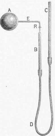
Fig. 3. - Jolly's Air Thermometer.
5. The method of pyrometry by the chemical decomposition of solids is described in the article Dissociation, and more detailed information may be found in Lamy's papers published in the Comptes rendus of the institute of France, vol. lxix., p. 34V, and vol. lxx., p: 393.
6. In measuring high temperatures by the heating of water with heated platinum or other metal, according to Pouillet's method, we heat to the temperature to be measured a mass of the metal and then suddenly immerse it in a mass of water. Knowing the weight of the metal and its specific heat, and the weight of the water and its temperature before and after the immersion of the metal, we can compute the temperature of the latter before its immersion as follows: Let m be the weight of the metal, c its specific heat, and t its high temperature before immersion in the water. Let m' be the weight of the water, and t' its temperature before the introduction of the hot metal. The specific heat of water is unity. The thin metallic vessel containing the water has a weight a, and its specific heat is 5. The thermometer which shows the amount of elevation of temperature of the water by the heated metal has a portion of its length heated; let us call the weight of this part of the thermometer e, and its specific heat d. Finally let be the temperature of water, metal, vessel, and thermometer after the immersion of the heated metal, and at the moment they have all reached the same temperature.
The metal in falling in temperature from t to d has lost t- degrees, and a quantity of heat equal to mc(t-). The water in being heated from t' to has gained in temperature -t' degrees, and a quantity of heat equal to m' (-t'). For a similar reason the vessel and the thermometer which partake of the heating of the water gain respectively ab(-t') and ed(-t'). Hence the whole quantity of heat gained is (m'+ab+ed)(-t'), or m1(-t') if we make m1=m'+ab+ed; m1 is then called the equivalent mass of water. In forming an equation between the quantity of heat received and the quantity of heat lost we have mc(t-)=m1(-t'); whence t, the temperature of the heated metal, is expressed by t = m1(-t')/mc+. In using this method Pouillet heated a ball of platinum in a crucible of the same metal, and the vessel containing the water had a wire cup in its centre into which the heated platinum mass was thrown. One of the elements of accuracy in this method is the precise knowledge of the specific heat of platinum at high temperatures. Pouillet made this a special study, and determined it up to 1,200° C., using an air thermometer in obtaining the successive temperatures.
To obtain precise results with this method requires careful attention to several operations in the process, such as allowance for loss of heat by radiation from the water vessel during the experiment, and loss of weight of water by evaporation after weighing it and after the immersion of the heated platinum. We have also to guard specially against the projection of water from the apparatus by the generation of steam by the hot platinum. 7. Becquerel's pyrometer, based on the strength of thermo-electric currents produced by heating the junction of two different metals, is an improvement on a similar one devised by Pouillet. Two wires, one of platinum and the other of palladium, each about two metres long and of one square millimetre of section, are firmly tied together with fine platinum wire for a distance of about a centimetre from their ends. The palladium wire is enclosed in a porcelain tube, while the platinum wire is on the outside of this tube, which is itself enclosed in another tube of porcelain.
The free ends of the palladium and platinum wires are soldered to copper wires which lead to a tangent galvanometer, and the junction of the copper and the palladium and platinum wires are immersed in melting ice to keep them at a constant temperature, so that no thermoelectric current can be generated in the apparatus except at the junction of the wires in the porcelain tube. In order to obtain the value of a high temperature, the end of the porcelain tube containing the junction of the wires is heated up to this temperature, and from the deflection of the galvanometer needle produced by the thermo-electric current thus produced we deduce the temperature of the junction of the wires. This apparatus, to be of any value, has to be graduated by exposing the junction of the metals along with an air thermometer to the same successive high temperatures, and thus fixing the relation connecting the indications of each apparatus with the corresponding temperatures. 8. Siemens's pyrometer is thus described by the inventor: "In order to realize a pyrometer by electrical resistance, it is necessary to rely upon the absolute measurement of the electrical resistance of a coil of wire, which must be made to resist intense heats without deteriorating through fusion or oxidation.
Platinum is the only suitable metal for such an application, but even platinum wire deteriorates if exposed to the direct action of the flame of a furnace, and requires an external protection. The platinum wire used has, moreover, to be insulated and supported by a material which is not fused or rendered conductive at intense heats, and the disturbing influence of the varying resistance of the wires leading to the platinum wire has also to be neutralized. These various conditions are very fully realized by the arrangement represented in fig. 4. Thin platinum wire is coiled upon a cylinder of hard-baked porcelain, upon the surface of which a double-threaded helical groove is formed for its reception, so as to prevent contact between the coils of wire. The porcelain cylinder is pierced twice longitudinally for the passage of two thick platinum leading wires, which are connected to the thin spiral wire at the end. In the upper portion of the porcelain cylinder the two spiral wires are formed into a longitudinal loop, and are connected crossways by means of a platinum binding screw, which admits of being moved up or down for the purpose of adjustment of the electrical resistance at the zero of the centigrade scale.
The porcelain cylinder is provided with projecting rims, which separate the spiral wire from the surrounding protecting tube of platinum, which is joined to a longer tube of wrought iron, serving the purpose of a handle for moving the instrument. If the temperature to be measured do not exceed a moderate white heat, or say 1,300° C.=2,372° F., it suffices to make the lower protecting tube also of wrought iron to save expense. This lower portion only, up to the conical enlargement or boss of iron, is exposed to the heat to be measured. Three leading wires of insulated copper united into a light cable connect the pyrometer with the measuring instrument, which may be at a distance of some hundred yards from the same. They are connected by means of binding screws at the end of the tube to three thick platinum wires passing down the tube to the spiral of thin platinum wire. Here two of the leading wires are united, whereas the third traverses the spiral, and joins itself likewise to one of the two former, which forms the return wire for two electric circuits, the one comprising the spiral of thin wire, and the other returning immediately in front of the same, but traversing in its stead a comparison coil of constant resistance.
By this arrangement of wires the effect of the varying resistances of the leading wires is completely neutralized, for both battery circuits comprise the leading wires up to the distant coil, and all variations of resistance by temperature to which the leading wires may be subjected affect both sides of the balance equally. The measuring instrument may consist of a differential galvanometer if to the constant resistance a variable resistance be added. If the pyrometer coil were to be put into a vessel containing snow and water, the balance of resistance between the two battery circuits would be obtained without adding variable resistance to the coil of constant resistance, and the needle of the differential galvanometer would remain at zero when the current is established: But on exposing the pyrometer to an elevated temperature, the resistance of its platinum coil would be increased, and resistance to the same amount would have to be added to the constant resistance of the measuring instrument, in order to reestablish the electrical balance. This additional resistance would be the measure of the increase of temperature, if only the ratio in which platinum wire increases in electrical resistance with temperature is once for all established.
This is a question which I shall revert to after having completed the description of the pyrome-tric instrument. Although I have stated that by means of a differential galvanometer and a variable resistance (constituting in effect a Wheatstone bridge arrangement) the increasing resistance of the platinum spiral may be measured, it was found that the use of a delicate galvanometer is attended with considerable practical difficulty in iron works and other rough places where it is important to measure elevated temperatures, or on board ship for measuring deep-sea temperatures. I was therefore induced to seek the same result by the conception of an instrument which is independent in its action from tremulous motion, or from magnetic disturbance caused by moving masses of iron, and which require no careful adjustment or special skill on the part of the operator. This instrument is represented in fig. 5, and may be termed a chemical resistance measurer or 'differential voltameter.' Faraday has proved that the decomposition of water in a voltameter, expressed by the volume of gases V, is proportionate in the unit of time to the intensity I of the decomposing current, or that I=V/T. According to Ohm's general law, the intensity I is governed by the electromotive force E, and inversely by the resistance R, or it is I=E/R. It is therefore V/T=E/R or V=ET/R; or the volume V would give a correct measure of the electrical resistance R, if only the electromotive force E and time T were known and constant quantities.
But the electromotive force of a battery is very variable; it is influenced by polarization of the electrodes, by temperature, and by the strength and purity of the acid employed. The volume of gases obtained is influenced, moreover, by the atmospheric pressure, and it is extremely difficult to make time observations correctly. It occurred to me, however, that these uncertain elements might be entirely eliminated in combining two similar voltameters in such a manner that the current of the same battery was divided between the two, the one branch comprising the unknown resistance to be measured, and the other a known and constant resistance. The volume of gas V, produced in this second voltameter, having a resistance R, in circuit, would be expressed by V1=ET/R1 and we should have the proportion of V:V1= ET/R : ET/R1; but E and T, being the same in both cases, may be struck out, and the expression will assume the simple form V: V1:: R: R1. The constant resistance R of the one circuit being known, it follows that the unknown resistance R1 is expressed by Rυ/V1; that is to say, by a constant multiplied by the proportion of gas produced in the two voltameters irrespective of time, or strength of battery, or temperature, or the state of the barometer.
The resistances R and R1 are composed each of two resistances, namely, that of the principal coils, which we may term R or R1, and of the voltameter and leading wires, which is the same in both cases, and may be expressed by y. The expression should therefore be written as follows: V: V1 = R1 + y1: R + y, R1 being the unknown quantity. The mechanical arrangement of the instrument will be understood from the diagram, fig. 5; and the whole arrangement of the pyrometer, with its leading wire and resistance measurer, from the general view given in fig. 6. The voltaic resistance measurer, fig. 5, consists of two calibrated vertical tubes of glass of about three millimetres diameter, which are fixed upon a scale showing- arbitrary but equal divisions. The upper ends of the tubes are closed by small cushions of India rubber pressed down upon the openings by means of weighted levers, whereas the lower portions of the tubes are widened out and closed by plugs of wood, through which the electrodes in the form of pointed platinum wires penetrate to the depth of about 25 millimetres into the widened portions of the tubes.
By a side branch the widened portion of each vertical tube communicates by means of an India-rubber connecting pipe to a little glass reservoir containing acidulated water, and supported in a vertical slide. In raising the weighted cushions closing the upper ends of the vertical tubes, and in adjusting the position of the small reservoirs, the acidulated water will rise in both tubes to the zero line of the scale. In turning a button in front of the tubes the battery current is passed through both pairs of electrodes, the one circuit comprising the permanent resistance R and the leading wires up to the pyrometer, and the other the leading wires and the pyrometer coil. If the resistance of the pyrometer coil should be equal to the permanent resistance R, then R1+y will be equal to R+y, and therefore V=V1; but as the resistances differ, so will the volumes. Necessary conditions are, that both reservoirs are filled with the same standard solution of pure water with about 10 per cent. of sulphuric acid, that all of the electrodes are of the same form and size, and that their polarity is reversed frequently during the progress of each observation, in order to avoid unequal polarization.
With these precautions, which involve no particular skill or knowledge of electrical observation on the part of the operator, very accurate results are obtained; but in order not to incur considerable error of observation, it is advisable not to continue the current, reversing the same, say twice, until at least 40 divisions of gases are produced in the least activated tube, which operation will occupy from two to three minutes, if a battery of from four to six Daniell elements is employed. The volumes V and V1 being noted, after having allowed half a minute for the gases to collect after the current has ceased, the weighted cushions upon the tubes are raised in order to allow the gases to escape, when the water levels will immediately return to their zero position, to make ready for another observation. By inserting the observed values for V and V1 into the expression above given, the unknown resistance R1 can be easily calculated; but in order to facilitate the use of the instrument, I have prepared a table which gives at a glance the resistance due to any two observed volumes, the volumes V governing the vertical, V1 the horizonal columns, and the resistance read off at the point of intersection.
At each point of intersection the resistance is marked in black, and the corresponding temperature in red ink. It now remains only to be shown what is the relation between the resistance and temperature in heating a platinum wire. The researches of Dr. Matthiesen, who has made the latest investigation on the effect of temperature upon electrical resistance, are restricted to the narrow range of temperatures between 0° and 100° C., nor do they comprise platinum. He adopted the following general expression for the pure metals: Rt=Ro/(1+xt+yt2) which, in determining the specific values of x and y for each metal, gives a close agreement with observation between the narrow limits indicated, but is wholly inapplicable for temperatures exceeding 200° C, when the value t2 commences to predominate and to produce absurd values for Rt. It was necessary for my purpose to undertake a series of elaborate experiments with a view of finding a ratio of general application. Coils of thin wire, of platinum, iron, copper, and some other metals, were gradually heated and cooled in metallic chambers containing the bulbs of mercury thermometers, and for higher temperatures of air thermometers, and the electrical resistances were carefully noted.
The progressive increase of electrical resistance was thus compared directly with the increasing volume of a permament gas (carefully dried) between the limits of zero and 470° C., and a ratio established which is represented by the formula Rt=αT2+βT+γ, in which T signifies total temperature counting from the absolute zero (272° C.), and α, β, and γ specific coefficients for each metal. According to this formula, the electrical resistance is a constant at the absolute zero, and progresses in a ratio represented graphically by a tipped-up parabola, approaching more and more toward a uniform ratio at elevated temperatures. Although the comparison with the air thermometer could only be carried up to 470° C., the general correctness of the ratio of increase just stated has been verified by indirect means in measuring progressive heats, and by comparison with the platinum ball pyrometer. It is important to mention here that great care must be exercised in the selection of the platinum wire for the measuring spiral, one of two samples, both of which were supplied by the same eminent makers, Messrs. Johnson and Mathey, having conducted 8.2 and the other only 4.7 times better than mercury at 0° C. The abnormal electrical resistance of some platinum wire is due chiefly to the admixture of iridium or other metals of the same group, and it appears that the platinum prepared by the old welding process is purer and therefore better suited for electrical purposes than the metal consolidated by fusion in a Deville furnace.
This pyrometer has already received several useful applications. Through its first application an important telegraph cable was saved from destruction through spontaneous generation of heat. Prof. Bolzani of Kazan has made some interesting applications of it for recording the temperature at elevated points and at points below the earth's surface. Mr. Lowthian Bell has used it in his well known researches on blast-furnace economy; and at several iron works pyrometer tubes are introduced into the heating stoves, and permanently connected with the office, where the heat of each stove can at all times be read off and recorded." Experience has shown that of all pyrometers, this is the best adapted for use in the arts. 9. By Mayer's pyrometer the expansion of the wave length of a definite sound, caused by elevation of temperature, is measured as follows: Opposite the mouth of an organ pipe is placed a Helmholtz resonator (see Sound), which responds to the note of the organ pipe. The sonorous pulses, emanating from the organ pipe, enter the mouth of the resonator, and are thence sent through a tube terminated by a spiral tube of platinum. The pulses which have passed through this spiral tube are led to one of König's vibrating manometric flames.
Another flame placed directly behind the former one is vibrated by pulses which have proceeded directly from the organ pipe. If the temperature in the organ pipe and in the spiral tube is the same (as is the case before the latter is introduced into the furnace), on viewing the flames in a rotating mirror we shall see both flames vibrating together and presenting the appearance of a deeply serrated band of light. Now, on slowly introducing the spiral tube into the furnace, we shall see the serrations, produced by the pulses which have traversed this tube, slowly sliding over the fixed serrations which are caused by the pulses led directly from the organ pipe to its special flame. After the air in the spiral tube has reached the temperature of the furnace and is stationary, we shall observe the serrations stationary also. From this observation of the number of movable serrations which have glided over any one fixed serration we can deduce the temperature of the furnace, as follows: Let t = temperature centigrade of the air in and around the organ pipe; t' = that of the air in the spiral or furnace tube; v = velocity of sound at temperature t; v' = that of sound at temperature t'; l = number of wave lengths in furnace tube at temperature t; d = observed displacement of resonator serrations by an elevation of temperature t' - t.
Then t', the temperature of the furnace, will be t'=(υl/20.16(l-d))2-272.48 which gives t' in terms of v, l, and d. For fuller details concerning this method see the "American Journal of Science" for December, 1872. The advantage of this process is that no correction has to be made for barometric pressure, and the precision of the method depends alone on the accuracy of the determination of the coefficient .00367, which is the number arrived at by Regnault and Magnus for the expansion of air under a constant pressure; and this is one of the most certain constants we have in physics. Hence, theoretically, this method is as accurate as that of the air thermometer. - For further information on this important subject of pyrometry, see an article entitled Pyrometrische Versuche, by A. Weinhold, in Poggendorff's Annalen, vol. xxix., 1873. In this the author gives the bibliography of the subject and details of his experiments with all pyrometers to decide their relative values in practice.

Fig. 4. - Siemens's Pyrometer, Coil Tube.
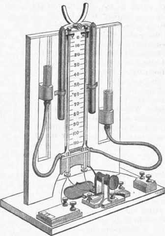
Fig. 5. - Siemens's Pyrometer, Resistance Measurer.

Fig. 6. - Siemens's Pyrometer, General View.
Continue to:
My Books

