Machine Shop Management. Part 12
Description
This section is from the book "Evolution Of The Machine Shop", by James Hartness. Also available from Amazon: Evolution Of The Machine Shop.
Machine Shop Management. Part 12
"any" machine.
Many important improvements in your product can be made without delay or expense if your machines are truly ready for turning every conceivable piece.
The description of the details of the machine which follows renders it possible to understand the various features of the machine. If it has been made clear that this machine indicates the direction in which the evolution of the lathe is traveling, there is no one, from the proprietor to the machinist, who can afford to be indifferent to the subject.
It is not safe for us to disregard important pointers of this character; and there can be little profit or benefit accruing to any one knowing these facts who fails to act accordingly. The foreman should strenuously advocate what he knows to be true. The superintendent's reputation suffers if he does not advise on correct lines, and the proprietor's profits, to say nothing about the depreciation of his permanent investment, will seriously suffer if he continues to use inferior machines. It is not enough to know that machines in operation were built yesterday; it must be known that they are of the correct type, for with so many machines offered for a given class of work, each machine cannot be the best; some one is better than all the others. Many companies may be wrecked in the future by conditions outside of their control, but we know that the companies that will survive will be only those that take advantage of cost-reducing methods, and that others, instead of being a source of income to the proprietors, will become white elephants, positive burdens that no one can afford to own.
Your success depends.
It is not within the scope of this chapter to answer all of the questions that will come to the mind of the man who has given this matter much serious thought and has heard claims for the old type reiterated. Each important point will be fully treated in the most fitting place. The foregoing pages present only a few of the many indications of direction of the evolution of the machine shop. A few more pointers will be found throughout the entire book, including that portion devoted to the commercial description of the machine. Therefore, you are urged to read all of the following pages.
Diagrams Illustrating Cutting Action
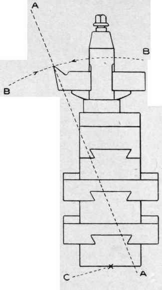
The cutting strain should be only in line with dotted line A to A in diagram on following page, which would keep a continuous strain on the cob-house, holding it away from the work, thus taking up all the slack and spring in one direction.
But the real facts of the case are that the tool must be very blunt and very unlike the tool shown in order to maintain a constant thrust. On steel work of small diameter the tool may be set a trifle above the center to maintain a constant backward thrust. The most trouble is experienced in working brass and other soft compositions. For such work it is very common to find tools without top rake. The edge-destroying motion is in line with dotted line B - B which is an arc struck from center of base at C.
Experience has demonstrated that the tool shown by Fig. 1 is the most effective in many lathes. The reason is that although
Exaggerated Cases of Cob-house Construction, Slide upon Slide there is a cutting strain of the chip in direction of arrow marked A, there is at the same time a lateral vibration (while under the cut-
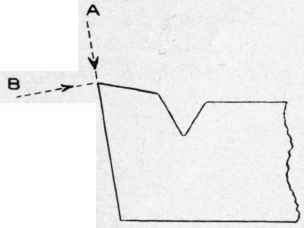
Fig. 1. A Common Form of Tool, Showing almost Level Top, a Tool with very Little Rake.
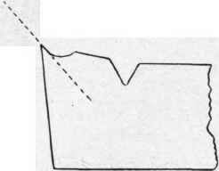
Fig. 2. An Exaggerated Case of a Tool, showing the.
Sharpening Action of a Chip, proving that the Tool should be Ground on the Angle Indicated by Dotted Line ting strain) in the direction of arrow B. This edge-destroying vibration is what has made it necessary to give the edge a strength or backing to meet this strain.
The hollow shown in Fig. 2 was worn in the tool by the chip because some condition prevented the vibration, which usually destroys the edge first.
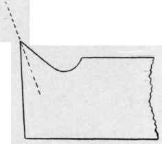
Fig. 3. Ideal Form of Cutting Edge for an Ideal Machine.
The dotted line indicating the line of thrust of cutting is in line with the tool's greatest strength.
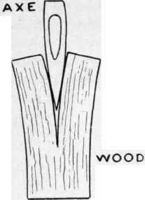
Fig. 4.
Stock removing is accomplished by a splitting action and finishing surface is produced by a scraping action of the tool.
The axe shown in Fig. 4, and the cutting tool in Fig. 5, are shown with cutting edge not in contact with the metal. Although these are exaggerated diagrams they tell a true story, as shown by Fig. 2.
In Fig. 5 we have another action which leaves a fair surface. This is the regular tool used so many years in the Flat Turret
Lathe with such satisfactory results. The chip is split from the face of the shoulder and is sheared off from the surface which is left on the finished diameter. This action of shearing is better than that of the average tool in other machines, for there is no pulling-out-by-the-root appearance to the finished surface. Furthermore, this tool is usually followed by the back rest, which burnishes the finished surface.
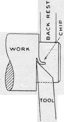
Fig. 5.
The shoulder from which the splitting cut is taken is rough until the tool is allowed to take a slight scraping cut after desired length has been turned.
The preferred form of tool for finishing is one which takes a diagonal scraping cut, as the cutter in Fig. 6 would take if it were ground like Fig. 7; that is, with rounded corner. The diagonal scraping cut is the kind taken by a spiral milling cutter. The
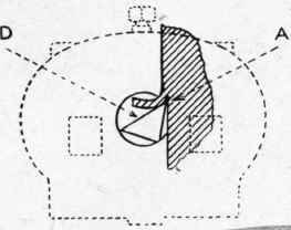
Fig. 6 diagram, Fig. 6, shows the ideal tool removing heavy part of chip by the splitting action at A and finishing with a diagonal scraping cut at D..
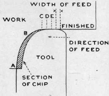
Fig- 7.
Fig. 7 gives top view of tool for chucking and other operations in which no back rests or other steadying means are employed. The chip from A to B is removed by splitting action; from B to C the cut becomes lighter and the angle of the tool becomes diagonal to the motion of the work.
The Home Of The Flat Turret Lathe The Hartness Flat Turret Lathe And Equipment, Protected By Twenty-One James HARTNESS PATENTS - OTHERS PENDING
Gold Medal Received At Paris In 1900 And Silver Medal Was Issued To The Inventor Both Awards Were The Highest Obtainable For A Single Exhibit Columbia Exposition In 1s93 Issued An Award For Superior Design
James Hartness. President VI. D. Woolson, Treasurer J. W Bennett, Secretary
Manufactured And Exclusively S0ld In America BY
Jones & Lamson Machine Company
Springfield, Vermont, U. S. A. And 97 Queen Victoria Street, London, England
M. Koyemann. Civil-Ingenieur (for Germany. Switzerland. Holland. Belgium, Aiifu-Hungary) Chahlotten Strasse, Ousseldorf, Germany
Copyright 1905 by the
Jones & Lamson Machine Company
Springfield, Vermont, U. S. A.
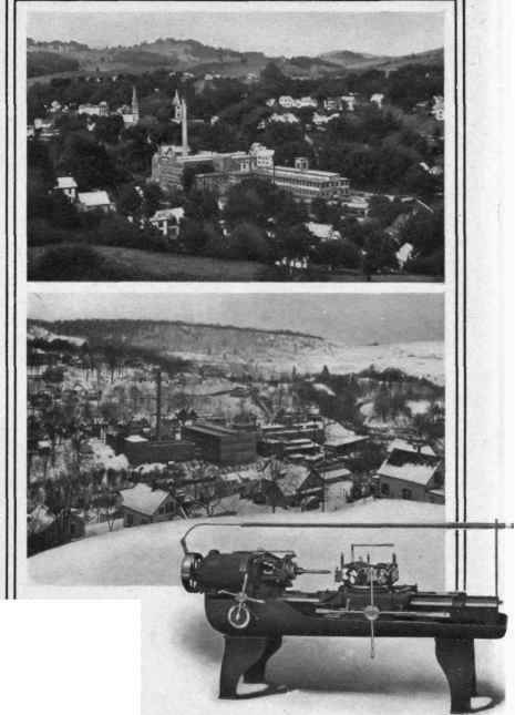
The Home Of The Flat Turret Lathe.

The frontispiece of this section gives a Summer and a Winter view of Springfield, Vermont, the home of the Flat Turret Lathe. In the foreground may be seen the buildings of the Jones & Lamson Machine Company, in which all of the Flat Turret Lathes now running in this country were built.
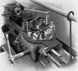
In the lower corner, with a snow bank for a background, is shown the present form of Flat Turret Lathe, to which the following pages are devoted.
The Flat Turret Lathe was the first machine for rapidly doing general lathe work and the first machine for accurately turning long, slender work without use of centers. Before its introduction there was no means for rapidly and accurately turning bar work having a length over ten or more times its diameter.
The working length of the original Flat Turret Lathe was 24 inches, and although this was a desirable feature, the strongest point in making friends was its simplicity and convenience of design, which made it possible to quickly adjust it for any kind of work within its limits, its product being true beyond the average product of the engine lathe and in quantity from three to ten times as great.
Since 1891 we have developed with care each feature of this machine and now illustrate its present form, which has already met with even greater favor than anticipated.
Fifty Years' Progress.

HE evolution of the Turret Lathe has been the result of work of many men and many companies, but this Company has made some of the important improvements. The principal steps of our fifty years' work are illustrated on the following page and may be summarized as follows:
1855 - We made the first turret machine known to us, having mechanism for automatically turning the turret.
1858 - We produced the present form of high turret with the turret-turning mechanism the same as the one now in universal use.
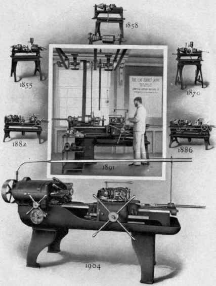
1870 - One of the links in the chain of evolution, showing an automatic chuck.
1882 - The first clutch back-geared machine.
1886 - The same in more symmetrical form.
1891 - The first Flat Turret Lathe.
1904 - The first Flat Turret Lathe with cross sliding head.
Continue to:
My Books

