Photophones
Description
This section is from the book "American Library Edition Of Workshop Receipts", by Ernest Spon. Also available from Amazon: American Library Edition Of Workshop Receipts.
Photophones
Fig. 101 illustrates the principle of Bell's photophone, and shows one of the most successful arrangements. A beam of light from any source is concentrated on the diaphragm a by the lens b, and the diaphragm of silvered mica or glass capable of reflecting the light is placed in such a position in relation to the lens 6 as to project the light along a line joining the ares of the lens c and of the parabolic reflector d. The lens c renders the divergent rays of light parallel, and the parabolic reflector concentrates the light upon the selenium cell e. The selenium forms a part of an electric circuit, which includes the battery f and receiving telephone g, A sound made in the vicinity of the transmitting instrument vibrates the diaphragm .. and undulates the beam of light projected through the lens c, and the consequent variations in the intensity of the light concentrated on the selenium by the parabolic reflector, changes the electrical conductivity of the selenium, and renders the electric current under . latory.
This current affects the receiv - ing telephone in the same way as it would be affected in an ordinary telephonic circuit, and the sounds made in the transmitting instrument are reproduced in the telephone.
Fig. 101.
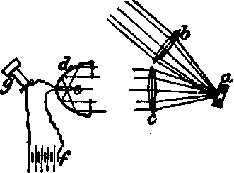
Fig. 102 shows the cylindrical form of selenium cell adopted, the rays of Modulatory light being thrown upon its cylindrical face by a paraboloid reflector, in whose focus it is placed." This beautiful little instrument consists of a number of circular discs of brass, about 2 in. in diameter, strung upon a rod passing through their common centre, and separated from one another by a similar series of discs of mica, whose diameter is slightly smaller than that of the brass discs, so as to form with the Utter (when the whole is built together as a cylinder) a number of grooves around its cylindrical surface. The discs are held firmly together by nuts and bolts passing through them, 2 of which are shown in the diagram, and which form the connecting screws for placing the instrument in circuit with a pair of telephones and a battery. Upon reference to Fig. 102 (which is only a diagram explanatory of the arrangement of circuits, and does not represent the construction of the instrument or the proportion of its parts), it will be seen that every alternate disc of brass is in metallic connection with the upper bolt, but is insulated from the lower bolt, and vice versa.
In other words, if all the brass discs were num. bered consecutively from one end of the series to the other, all the discs marked with even numbers are connected to the lower bolt and insulated from the upper, and all the uneven - numbered discs are in contact with the upper bolt, but insulated from the lower. The grooves formed around the cylindrical surface are filled in with selenium by the following simple process: the cylinder is first heated to a temperature somewhat above that of the fusing - point of selenium, and, while hot, a stick of selenium is rubbed over its surface, filling up the grooves and covering the edges of the brass discs. The cylinder is then put in a lathe, and the selenium is turned off until the edges of the brass discs are bared. Before being sensitive to light, however, the selenium has to be annealed by first heating it until signs of fusion begin to show themselves; when the heat is removed, the fused portions recrystallize, and the selenium is thereby rendered both sensitive to light and a conductor of electricity. Prof. Bell states that the whole process of annealing occupies only a few minutes. Fig. 103 is a diagram in which the connection of the brass discs with the external or telephonic current is more clearly shown.
Here it will be seen that the discs numbered 1, S, 5, 7, and so on, are connected to one terminal of the telephone t by the wire m, while S 2 the even discs 2, 4, 6, 8, 6c, are in connection with the other terminal through the wire a and battery b. Upon examination of the diagrams, it will be seen that while the surfaces of contact between the selenium rings and the brass discs are increased to a maximum by reason of their large diameter, which also ensures a maximum of sensitive surface, the resistance of the whole photopile is reduced to a minimum, not only by the method of making the circuits as shown, but by the large sectional area of conducting material presented by the annular form of the selenium. The transmitting instrument of the photophone is shown in fig 104, and consists of a long board mounted upon a firm support (with suitable adjustments for directing it, within certain limits, in both altitude and azimuth), to which are attached the various parts of the apparatus : o is the mouthpiece with its reflecting diaphragm d of silvered glass or mica, and m is the mirror by which a ray of light from the sun or any other powerful source may be projected on to the diaphragm d by the condensing lens /, below which is fixed another lent for the purpose of parallelizing the beam after reflection from the silvered diaphragm, and projecting it to the distant station, where it is received by the paraboloidal reflector of the receiving instrument, in the focus of which is placed one of the cylindrical photopiles such as described, and In circuit with the latter is placed a pair of telephones and a voltaic battery, which in Prof. Bell's experiments consisted of 9 Leclanche ceils.

Fig. 103.
Fig. 105.

Prof. Bell made a series of photophonic experiments in Paris, using the electric light as his source of illumination, and it is an interesting fact - although one which might have been expected from the results obtained in his earlier experiments - that the irregularities and vibrations, which are well - nigh inseparable from the light emitted by the electric arc, produce their effect in the tele - heard superposed, as it were, upon the "voice"of the arc.
Fig. 105 is a diagram illustrating the arrangement of apparatus with which Prof. Bell worked in Paris. l is the electric lamp, the arc of which is in the focus of a parsbnloidal silvered reflector m, by which the divergent rays emanating from the arc are condensed and projected as a parallel beam to the reflecting diaphragm d, by which a certain small proportion of them is reflected to the receiving instrument through a distance of nearly 50 ft., as shown in the figure. From this diagram it will be seen that a very large proportion of the light projected by the lamp reflector does not fail upon the diaphragm at all, but notwithstanding this loss, highly satisfactory results were obtained in the transmission of articulate speech, and Prof. Bell is of opinion that effects equal to those obtained with sunlight would be produced by means of an electric lamp suitably arranged so as to utili2e the whole of the light radiating from the arc. (Engineering.)
Continue to:
My Books

