A Small Electric Motor
Description
This section is from the book "Amateur Work Magazine Vol1". Also available from Amazon: Amateur Work.
A Small Electric Motor
Donald M. Bliss.
The small electric motor illustrated herewith is well adapted for operating model electric cars and light machinery. It will not develop more than 1/20 horse-power. It can be driven to the best advantage by five or six cells of bichromate battery or ten to twelve cells of gravity battery. It will also operate satisfactorily for short intervals on eight and ten cells of the Leclanche or a similar type of battery. Of course in the latter case it must be remembered that .such a battery is only suitable for intermittent work, and cannot be relied upon to run the motor for more than a few moments at a time. It is exceedingly simple in construction and consists practically of only three parts: the base, magnet frame and armature. The base and magnet frame (see Fig. 1) should be made of soft cast iron. The frame should be secured to the base by four screws, as shown. The holes for these screws in the frame should be about 1/16" larger than the screws, to allow for a slight adjustment in any direction. The corresponding holes in the base should be drilled and tapped for a 10-24 round-head machine screw.
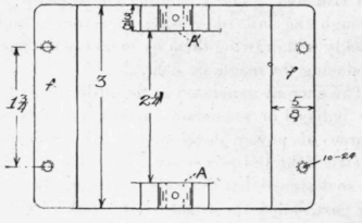

Figure 1
The surfaces of the base and corresponding part of the frame may be ground, filed or planed so that when the parts are assembled the holes in the bearing standard A,A' should be exactly in the center line of the field bore B. If clean, sharp castings can be secured, it will not be necessary to bore out the field frame B. If it is impossible to secure good castings, this base should be bored out, as shown, to the diameter of 113/16". The armature shaft D is simply a straight piece of quarter-inch soft steel rod, which should be filed and polished until it fits easily and freely the bearings A,A'. These bearings should be drilled, using care to see that they are lined squarely across the base. An oil hole in each standard should be drilled at the same time.
The armature E should also be a soft iron casting, and is provided with three poles and coils, as shown. The head of the armature is extended sufficiently on one end to carry a three-part commutator, F, while the other end is prolonged so as to form a bearing shoulder when the armature is placed on its shaft. It may be found necessary to turn the armature, if the casing is not true, to a diameter of 13/4|". After the hole in the center of the armature for receiving the shaft has been drilled, it should be mounted on an arbor and accurately turned in a lathe to the required size. When this is done, go over the castings carefully, file away all sharp points and corners, so that when the wire is wound on there will be no danger of injuring the insulation.'


Section through A-B
Figure 2.
Then cover the three arms of the armature carefully with two layers of thin cotton cloth. This can be held in place by winding a few turns of thread around the various parts and painting them well with shellac varnish. When thoroughly dried, each limb of the armature should be wound with from forty to fifty turns of No. 20 single cotton-covered magnet wire, leaving several inches of wire at each end for connections. The inside ends of the coils thus formed should be twisted together and soldered, while each of the outside ends should be connected to one of the three segments on the commutator. These connecting ends should not run down straight to the commutator, but should be left long enough so as to admit of turning the commutator on its bearing in either direction, to allow for correct adjustment. The commutator itself may be made of a short piece of \" brass or copper tubing, sawed apart so as to form the three segments as shown. These segments are mounted on the hard rubber or fiber sleeve, G. In this sleeve is bored a 3/8 hole, so that it may be mounted on the extended hub of the armature, as shown. If fitted tightly on the shaft, it will not be necessary to use set screws to hold the sleeve in place. If necessary to use a set screw, it should be drilled and tapped into the fiber, and not touch one of the segments of the commu tator, as this would injure the winding of the armature, and possibly lead to a short circuit or ground.

Figure 3.

Figure 4.
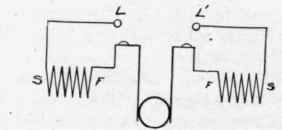
Figure 5.
Referring again to the field frame (Fig. 2), the two field coils, II and H', may be made. Each coil consists of about four ounces of No. 18 single cotton-covered magnet wire. This may be wound upon a wooden arbor about 1/8" longer and wider than the field coils, which, it will be noted, are 11/2" xl" in section. This winding arbor should have two heads turned and screwed thereon, so as to leave a winding space of the same size and section as the coil. A space 1/2" wide x 1/2" deep will be found sufficient for this. Before starting the winding of these coils, lay three or four strips of thin tape 6" long across the winding space on the arbor, and wind the wire carefully in even layers in this space. After the required amount has been wound on, the tape may be tied together tightly, one of the heads taken off, and the coil removed from the arbor. Before fitting the coil on the pole-piece, it should be wrapped all over with two layers of thin cotton tape, so that the wire will not be exposed at any point. The coils should then be well painted with shellac varnish, and allowed to dry before being placed on the frame. The two coils are held in place, when mounted on the pole-pieces, by wooden cleats forced in between them, as shown at I.'.

Figure 6.
The terminal board and brush-holding device is shown by Fig. 4, and is made of a block of fiber or hard wood, of the dimensions shown. The brushes K,K' are simply two strips of hard-rolled copper about \" wide and 1/32" thick, bent at right angles, and mounted in such a position that when the terminal block is fastened to the top of the frame, as shown in Fig. 6, they will touch on the opposite sides of the commutator in a vertical position. The connecting terminals of the motor L-L are simply two short machine screws provided with copper washers. These screws are drilled and tapped into the fiber head, but should be placed so as not to bear on the iron frame, otherwise a short circuit will result.
See that the armature is centered in the frame, so that it will revolve freely with an equal clearance from the pole-pieces at all parts of its diameter. This clearance will not be less than 1/32". Adjust the armature on the shaft so that it turns freely and is central with the poles. The armature may be held in position on the shaft by a set screw or by making a snug driving fit.
If the foregoing directions have been properly followed, the motor may be now connected up, as shown in Fig. 5.
The wire is run from the binding-post L, and connected to the inside end of one of the field coils. The outside end of the same coil is carried up and connected to one of the brush-holding screws. Another wire is run from the remaining binding-post to the inside end of the other field coil, and the outside end of the same coil is connected to the remaining brush-holding screw. This connection is clearly shown in Fig. 5, and when so arranged is termed "series" winding. This is the most suitable connection for a motor of this type and size. Any deshred form of pulley, or a small gear, may be fitted to the outside end of the armature shaft, and the motor is ready to run.
If it does not start promptly at first, the commutator may be turned slightly on the shaft in one direction or the other until the best position is found which will give the greatest turning power with the least amount of sparking. Being a series-wound machine, the speed will be constant only under a steady load. Great care should be taken to see that all the windings are thoroughly insulated from the frame or other metal parts, and when the machine is completed it should be given a coat of light enamel paint, which will improve its appearance and prevent rust. The commutator and brushes should be kept clean and free from oil.
Do not attempt to run this motor directly from an electric-light circuit. If it is desired to produce such a current, it should be as connected in the series, with a sufficient amount of resistance to cut the current down to an amount equal to that derived from the battery. It is necessary, both for ease of construction and to secure efficiency, that the castings composing the frame and base be of soft iron. If this point is not attended to, you will probably get iron castings so hard that it will be almost impossible to work them, while the operation of the motor will be unsatisfactory. Unless you are familiar with metal working in the lathe, it will be advisable to have the fitting and centering of the parts done by a machinist. The expense for this will not be large and should not deter one from building the motor. If you are the fortunate possessor of a small engine lathe, you can easily do all the work yourself.
The construction and operation of this little motor will give you a good insight into the operation and principles involved in motor construction, and it will be found very convenient in driving model machinery. The battery described in the December number of Amateur Work, with the cells in series grouping, is well adapted for operating this motor at its full output. If gravity battery only is available, it is advisable to wind the armature and field coils with fine wire, No. 24 B & S gauge for the armature and No. 20 for the fields. As the greatest output to be expected from twelve cells of gravity battery would be twelve volts, at less than one-half an ampere or something under six watts, it is evident that only a small amount of power can be derived from a battery of the gravity type. The ordinary open circuit or Leclanche battery with large zincs will deliver fully twice as much current, but, as stated above, only for momentary work, owing to the rapid polarization of this type of battery. The most satisfactory results can be obtained from the bichromate battery, which you can easily make yourself.
Continue to:
My Books

