77. Rake Moldings
Description
This section is from the book "Constructive Carpentry", by Charles A. King. Also available from Amazon: .
77. Rake Moldings
Rake Moldings. (A). The method of finding the shape of rake moldings is illustrated in Fig. 112, all of the moldings but the regular patterns being worked out by hand if there is no mill conveniently located where cutters may do it, though even then it is often more economical to work the molding out on the bench if properly shaped molding planes are available. Worked rake moldings are not used so much to-day as they were formerly, as upon common buildings the eaves are so designed as to make them unnecessary.

Fig. 112. - Laying out a Rake Molding.
The molding ab governs the shape of the others, and is used upon the level eaves; it should be drawn at the angle at which it will rest in relation to the level, and working lines should be drawn from it, at the pitch of the gable. The molding cd is the pattern used upon the gables, or the pitch of the roof. The molding ef is to be used upon the finish of the upper edge of a shed roof, though this form of rake molding is rare.
The lines, 1, 2, 3, etc.. are for the purpose of determining the points which give the contour of the moldings, and in every case they are the same distance from the back line, .xd, and xf, as from the line xb.
The rake cornice and molding upon a moderately expensive house are often put on as shown in Fig. 113, the ends of the rafters being square with the pitch of the roof, and the facia mitered around it, upon which the molding is nailed. By many carpenters this method is considered neither architectural nor workmanlike; it certainly permits quite a saving in labor, and aside from appearances is quite as efficient : it is used upon many good buildings.

Fig 113. - Rake Box Cornice.
(B.) The method of making a miter box for the sawing of rake moldings is shown in Fig. 114, in which c, a, b, of A shows the plan of the house, and ad the miter of the molding; the diagram, a1 b1 c1 d1 shows the method of finding the miter if the building is not rectangular in plan. B shows the pitch of the roof, and b a z the plumb cut of the mitered corner, which is the same as that for common rafters. C shows the top view of the miter box, the angle bad of which equals the angle bad of A, according to the angle of the corner of the house. A line, squared across the miter box from d, gives x; for a square house, ax will equal the width of the box.
D shows the edge view of the miter box, the angle baz of which equals the angle baz of B. Draw the line ax, of C, square with az and line xy, parallel with line az, and therefore square with line ax.
E shows the angle which is the miter of the rake molding, in order to obtain which, ay, of D, is laid off upon box E, and a line squared across the box as at wy; by connecting a and w, we have the miter. Thus, za of D, and aw of E, will give the down or plumb cut and miter of the gable piece of the rake molding; the horizontal, or eaves piece being cut in the miter box to the angles shown in bad of A. For a square corner this latter cut may be made in a common miter box. It is not necessary to make a separate box for each cut, as one box three or four feet long will be ample for any job of cornicing. For cutting the rake miter of the other end of the eaves, the cuts should be made the other way, or the molding cut the other side up, though unless great care is used this method is apt to give unsatisfactory results.
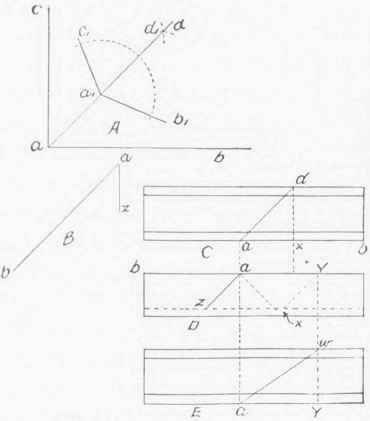
Fig. 114. - Rake Miter Box.
Some mechanics make a deep box with the ordinary miter cuts, and hold the rake moldings at their angles when in position, as the horizontal angle of each miter joint is always the same upon corners of the same horizontal plan or angle.
Continue to:
My Books

