How To Make An Electrical Anemometer
Description
This section is from the book "Handy Man's Workshop And Laboratory", by A. Russell Bond. Also available from Amazon: Handy Man's Workshop And Laboratory.
How To Make An Electrical Anemometer
The velocity of the wind is usually measured by noting the rate of rotation of a small wheel driven by the wind. In the instrument described below, the pressure of the wind is used as a measure of its velocity. A thin board is backed by a spring, which is held into the wind by a vane. The compression of the spring is determined by means of a weighted cord attached to the board and which passes through a tube to a convenient location within the building. In Fig. 172 the board againsl which the wind presses is indicated at A. It must be 1 font square, and is preferably made of 1/4-inch stuff and secured to a brass tube B 30 inches long by means of two nuts, one at each side of the board. The vane C is cut from a board 30 inches long by 6 inches wide and 3/4 of an inch thick. A piece of strap iron, D, is fastened to one end of the board, and projects above it. A hole is drilled through the strap iron to receive the tube B, which rides over a roller, E, and under a second roller, F, fastened on the upper edge of the vane. Between the board A and the strap iron is a brass spring of No. 15 wire about 16 inches long, which loosely fits over the tube B. The vane is mounted on a pipe G, which passes up through the roof of the building. Three screw-eyes are secured. The shank of one is chipped off", leaving a ring which is soldered fast to the pipe at H, forming a collar thereon to prevent the vane C-from sliding down the pipe. The other two screw-eyes, I, are fitted over the pipe G after being screwed into the board C through holes in strap iron D A small pulley, /, is secured to the board C directly over the pipe (7. and a cord. K, of suitable length attached to the board A passes over this pulley and through the pipe to the indicating mechanism within the building.
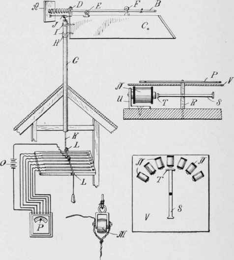
Fig. 172 - Details of the electrical anemometer.
According to statistics recently published, the wind pressure to the square foot at different velocities is as follows:
10 nines per hour...................... 0.37 pounds
15 miles per hour...................... 0.76 pounds
20 miles per hour...................... 1.27 pounds
25 miles per hour...................... 1.90 pounds
30 miles per hour...................... 2.64 pounds
35 miles per hour...................... 3.50 pounds
40 miles per hour...................... 4.44 pounds
45 miles per hour...................... 5.50 pounds
50 miles per hour...................... 6.66 pounds
55 miles per hour...................... 7.80 pounds
60 miles per hour...................... 9.22 pounds
By attaching a weight to the cord K of say 1.90 pounds, we will be able to determine how much the board A will be pressed back out of its normal position by a wind of 25 miles per hour. A board should be placed at a suitable position in the building, with a pulley, L, at each end to guide the cord across it. A small brass roller, M, should be introduced into the cord between the pulleys L. The method of attaching the roller is indicated in the enlarged detail view. On the board over which the roller is adapted to pass are a number of brass bars, each electrically -connected to a separate magnet .V, while the other terminal of each magnet is connected to the battery 0, and the circuit is thence continued by a wire running to the roller M. In this way, as the plate A is forced back, the roller M travels across the brass bars and successively energizes the magnets N. These magnets are placed under a dial face, and an armature is pivoted before them in such a way as to be attracted by the energized magnet, causing a needle P to move over the dial face and indicate thereon the velocity of the wind, as shown by its pressure against the plate A.
The weights, which must be fastened to the cord in order to show the location of the brass contact bars, may be made as follows: Procure a piece of thick cardboard, and trim it until it weighs exactly a quarter of a pound. Then divide the cardboard into 25 equal parts, and each part when it is cut out will weigh approximately 1/100 of a pound. With these small weights it will be an easy matter to make up the weights called for in the table above to represent the pressures at the various wind velocities. A small sinker should be tied to the end of the string, to keep it taut. A 1/4-ponnd weight and twelve of the 1/100-pound weights, making 37/100 in all, are now tied to the end of the string, and a pencil mark is made on the board where the roller touches it. This shows where the first contact bar should be placed, representing a wind velocity of 10 miles per hour. In the same way the positions of the other bars are found. To eliminate errors due to stretching of the cord K as the heavier weights are attached to it, a second cord may be used to carry the weights by which the board A is drawn back while the positions of the contact bars are being determined.
To make the indicating instrument, procure a piece of jeweler's tubing with an outside diameter of not over 3/32 of an inch and an inside diameter as large as an ordinary hatpin. The tubing R is fitted into a hole in the center of an ordinary nail, S, and the pointed end of a hatpin is driven into the baseboard of the instrument through the tubing to form a center for the armature S to revolve upon. A short piece of soft iron is soldered to the end of the nail at right angles as shown at T. The magnets N are mounted on small brackets U, with their poles facing the center of the armature and in close proximity to the path of the piece T as it is swung about. The needle P, which is soldered to the upper end of the tubing R, will travel with the armature over the dial face V, which is graduated to show the various wind velocities.
Continue to:
My Books

