Arches - Plane. Continued
Description
This section is from the book "Modern Buildings, Their Planning, Construction And Equipment Vol5", by G. A. T. Middleton. Also available from Amazon: Modern Buildings.
Arches - Plane. Continued
Equilateral Arches
Fig. 99 shows an arch in which the centres fall on the springing points A and B. In this case the triangle Abc is equilateral, and hence such an arch is termed an Equilateral Arch.

Fig. 98.
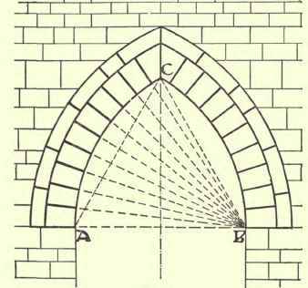
Fig. 99.
Depressed Or Drop Arches
This name is applied to pointed arches with the centres within the abutments, as in Fig. 100.
The joints in all three cases radiate as shown from the centres from which the arches are struck.
Four-Centred Arch
Fig. 101 shows the method of setting out a four-centred arch. The centres of the lower portion of the arch are on the springing line, while the centres of the upper portions are below it.
The joints must radiate from the centres from which the curves are struck, as shown in the figure. It should be observed that Fig. 101 shows but one case of the infinite number of four-centred arches that may be found. So long as there are two centres such as A and B upon the springing line, and two centres such as C and D below the springing line, D being collateral with A, and C with B, a satisfactory four-centred arch may be drawn.

Fig. 100.
Parabolic Arches
Let AB (Fig. 102) equal the span, and draw FD bisecting AB in C and perpendicular to it. CD is the rise and CF is made equal to CD.

Fig. 101.
Take a point E on AB produced, make EA = AC, and join ED and EF. Divide EF and ED into any convenient number of parts in 1, 2, 3, 4, 5, etc. Join 6 to 6. 5 to 5, 4 to 4, etc. A curve drawn tangentially to all these lines will be a parabola. Half this curve is used for one side of the arch In Fig. 102. The other half of the arch from D to B has been found by the same method.
Arches are sometimes made of the form shown by the curve Daf placed vertically.
To find any joint of the voussoirs of the arch, divide the intrados up as before, and from each of these points drop perpendiculars on to AB the springing line, such as GH on the right-hand side of Fig. 102. Produce CB to K, make BK = BH. Join KG. Then KG is a tangent to the curve; and at K erect a perpendicular to GK. This will be the pitch of a joint at point G. The pitch of the joints at all the other points is found in a similar manner.

Fig. 102.
Hyperbolic Arches
Let AB (Fig 103) be half the span and BC the rise. Draw AE = 2/5 of CB, and parallel to it. Join EC. Divide AE and CE into the same number of equal parts, as I, 2, 3, 4, etc. Join 1 to 1, 2 to 2, 3 to 3, etc.

Fig. 103.
A curve drawn tangentially to these lines will give the outline of the intrados of the required arch. The direction of the joints is found as shown for parabolic arches.
Another method of striking a similar curve is shown in Fig. 104. Let AB be the 1/2 span, and BC the rise. Prolong AB to D. Make AD - AB. Draw CE parallel and equal to AB. On CB mark off any number of equal parts in points 1, 2, 3, 4, etc., and join these to D. On CE mark off the same number of equal parts and join them to A. A line drawn through the crossings of these lines as shown on the left-hand side of Fig.
104 will give the curve of one side of the arch. The other side can be found in the same manner.
Ogee Arches
These arches are variously described as of 1, 2, 3, or more parts or divisions of the span or opening.
To draw an ogee arch of one part. Let AB (Fig. 105) be equal to the span or opening at the springing line, and bisect it in C. Draw CD, the centre line, at right angles to AB. Let E be the most prominent point of the hood-mould, as shown on the section of the moulding, and with centre C describe a quadrant EF. Bisect the quadrant EF in G. Through G draw EG prolonged to cut CD in H. Draw HK parallel to AB, and through G draw Cgl, cutting HK in L. The point L is the centre of the upper or reverse part of the ogee arch.

Fig 104.
For an ogee arch of three parts divide the span into three parts (see Fig 106). Find the centre C as before, and erect a perpendicular CD. Then with centre C and radius CE describe the quadrant EF, and divide EF into four equal parts. Join E to G, the last division of EF, and produce to cut CD at H. Through H draw HK parallel to EC. Join CG and produce to cut HK in K. This fixes the centre for the upper part of the ogee. In this instance the ogee is flattened, and naturally becomes more so the more points the span is divided into.

Fig. 105.
The design of ogee arches admits of infinite variety. Thus in Fig. 107 an arch is shown in which a similar process is employed to that described above, but AB,

Fig. 106.
BC, and CD have all been made equal; while in Fig. 108 an arch is shown where the span has been divided into eight equal parts, the centres taken where shown, while the lower curves are divided into five equal parts.
The object of taking the most prominent point of the hood-mould when striking the lower arcs is to make the mitre at the apex work conveniently. This, however, though usual, is not a hard and fast rule, and the lower arcs may be taken from any other point if the design permits of it.
Flat Arches
The use of a whole stone without joints, i.e. a lintel, is the most economical method of carrying a load over a small opening. Where, however, openings are large, - or from the nature of the stone scantling lengths are inadmissible, - various systems of jointing are practised, as shown below.
Radiating Joints (Fig. 109). - In this case the skew-backs are projected down to meet at the point C, from which the dotted curve AB is struck. The arc is divided up into an odd number of equal parts as in the case of a segmental arch. Lines radiating through these points from centre C mark the joints.
Stepped Joints
The same method is adopted in the case of stepped joints (Fig. no). The joints are, however, not continuous, but, as the name implies, are rebated or stepped. The work is more expensive, but is certainly very stable.

Fig. 107.
Joggled Joints
Another form, somewhat similar, is termed joggling, and consists in leaving a rounded projection on one face of the joint, and a hollow on the corresponding face of the adjacent stone, as shown in Fig. 111. This is perhaps more applicable to terracotta work.

Fig. 108.

Fig. 109.

Fig. 110.

Fig. 111.

Fig. 112.
For small openings some method such as is shown in Fig. 112 may be adopted. This is expensive on account of waste of stone in working, but it gives a very fine effect when well treated.
To set out the stones for cutting to the shapes required for the various positions of a square-headed window, see Fig. 113, which shows the elevation of a window head formed as a flat arch. In order to show the method of working the stones, take, for example, the angle stone Aibcd, whose elevation is its face mould. The bed mould Adfe is simply a plan of the above Aibcd with the moulding and rebate worked upon it.
The joint mould would be a projection on the raking plane IB, making the moulding somewhat elongated. This joint is set out by applying the mould to the square end of the stone, as shown by the dotted line IK, and cutting the mouldings back to the mitre line IH, the vertical portion of the moulding being worked up from the bed to meet a line drawn horizontally from the point I, and then continued as necessary to form the mitre with the horizontal moulding. The bevel is then set to the raking plane IB and the stone cut back to the joint.
To illustrate this more clearly, Fig. 113 shows an isometric view of the stone Aibcd, the plane face B1C1D1 representing the similarly lettered face Bcd on the face mould.
The letters A1 K1 Y, and V represent angles of the squared block from which the stone is cut, which have to be removed in bringing the stone to its required form.

Fig. 113.
Continue to:
My Books

