Electro-Magnetic Electricity. Part 2
Description
This section is from the book "Electricity For Boys. The "How-To-Do-It" Books", by J. S. Zerbe. Also available from Amazon: Electricity for Boys.
Electro-Magnetic Electricity. Part 2
The Dynamo Fields
Two of these spools are so made and they are called the fields of the dynamo.
We will next prepare an iron bar (I), 5 inches long and ½ inch thick and 1½ inches wide, then bore two holes through it so the distance measures 3 inches from center to center. These holes are to be threaded for the ¾-inch cores (A). This bar holds together the upper ends of the cores, as shown in Fig. 23
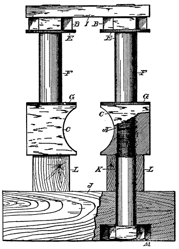 Fig. 23. Base and Fields Assembled
We then prepare a base (J) of any hard wood, 2 inches thick, 8 inches long and 8 inches wide, and bore two ¾-inch holes 3 inches apart on a middle line, to receive a pair of ¾-inch cap screws (K), which pass upwardly through the holes in the base and screw into the pole pieces (C). A wooden bar (L), 1½" × 1½", 8 inches long, is placed under each pole piece, which is also provided with holes for the cap screws (K). The lower side of the base (J) should be countersunk, as at M, so the head of the nut will not project. The fields of the dynamo are now secured in position to the base.
 |  |
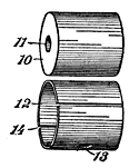
| Figs. 24-25. Details of the Armature |
The Armature
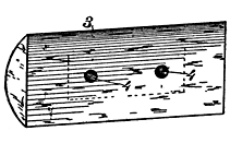
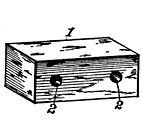
A bar of iron (Fig. 24), 1" × 1" and 2¼ inches long, is next provided. Through this bar (1) are then bored two 5/16-inch holes 1¾ inches apart, and on the opposite sides of this bar are two half-rounded plates of iron (3) (Fig. 25).
Armature Winding
Each plate is ½ inch thick, 1¾ inches wide and 4 inches long, each plate having holes (4) to coincide with the holes (2) of the bar (1), so that when the two plates are applied to opposite sides of the bar, and riveted together, a cylindrical member is formed, with two channels running longitudinally, and transversely at the ends; and in these channels the insulated wires are wound from end to end around the central block (1).
Mounting The Armature
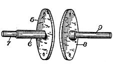
It is now necessary to provide a means for revolving this armature. To this end a brass disc (5, Fig. 26) is made, 2 inches in diameter, ⅛ inch thick. Centrally, at one side, is a projecting stem (6) of round brass, which projects out 2 inches, and the outer end is turned down, as at 7, to form a small bearing surface.
 |  |
| Figs. 26-27. Armature Mountings |
The other end of the armature has a similar disc (8), with a central stem (9), 1½ inches long, turned down to ¼-inch diameter up to within ¼ inch of the disc (7), so as to form a shoulder
Continue to:
My Books

