Laboratory Apparatus. Liebig Condenser
Description
This section is from the book "American Library Edition Of Workshop Receipts", by Ernest Spon. Also available from Amazon: American Library Edition Of Workshop Receipts.
Laboratory Apparatus. Liebig Condenser
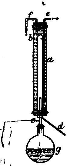
This condenser (Fig. 7) is much more compact, and is equally as effective as the ordinary form. Much valuable space is saved, which the chemist may use to better advantage, a is a tube about 2 3/4 in. diameter, and 20-24 in. long. 6 is a tube If in. diameter, closed at the upper end. This tube is fitted to the large tube by a thick heavy cork soaked in melted paraffin. The tube e, which reaches nearly to the bottom of the condenser, serves as an inlet for cold water, and f the outlet for the heated water. The tube c, connected with the flask g, carries the hot vapours to the condenser, where they are condensed and delivered by the tube d to any suitable receiver. The tube c, which is connected with a cork to the condenser, should pass up 2-3 in. beyond the cork to prevent the condensed vapours from passing back into the retort flask.
If properly constructed this condenser is very effective. Very little trouble will be experienced by the vapours condensing in c, and running back; so little surface is exposed to the cold atmosphere and cork connection. The vapours condensing in 6 run down the walls of the tube, and are completely delivered by the smaller tube d.
This condenser is admirably adapted for the distillation of nearly all liquids of low boiling points, which do not form explosive vapours, to come in contact with the flame under the flask g. However, highly volatile liquids like the ethers may be safely distilled by screening the receiver from the heat of the flame, and by connecting with the receiver a safety tube delivering the vapours escaping out of a window, or through a partition into an adjoining room.
Llebig condenser.
I usually employ as a safety connection, in the distillation of highly volatile and combustible liquids, a tube connected with the receiver, the extreme end of which dips under mercury, covered with a layer, 1 in. deep, of oil of a suitable character. This arrangement I have found perfectly safe; any escaping vapours are absorbed by the oil. (Chas. B. Gibson.)
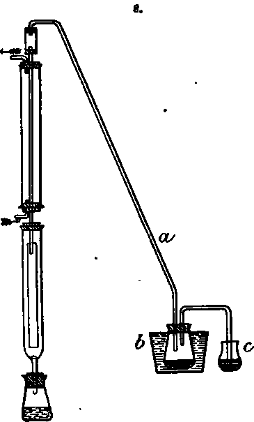
Safety Valve for Extraction Apparatus (Fig. 8).- Used very successfully when it is desirable to run the extraction for some hours, at the same time the attention being devoted to other work. The tube a is connnected with the Liebig as shown, and with the flask 6, which is loaded with mercury, and immersed in a vessel of cold water. Another tube passes from 6 into c, which is partly filled with mercury and oil. This apparatus is perfectly safe, as any vapours of the ether or benzine, which may not become condensed in the Liebig and flask o, will surely be absorbed by the oil in c. I have run this apparatus continuously for 24 hours, and have scarcely been able to detect even the smell of ether at c. I have no fear of accidents, even with high heat from a Bunsen burner, when these precautions are taken. (Chas. B. Gibson.)
Wire Apparatus For Laboratory Use
Before the year 1351 everything known as wire was hammered out by hand, but at that date or thereabout the art of wire drawing was invented. Since then the art has been developed and expanded, so that at the present time wire drawing is a leading industry, and we have wire of every size and shape made from all the ductile metals, and used in an infinite number of ways.
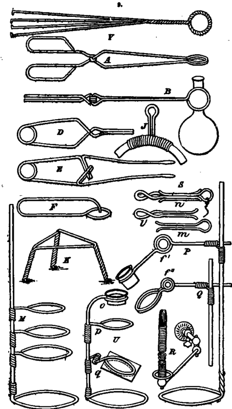
It is not my purpose to enter into an extended treatise on wire, but simply bring to the notice of the reader several new as well as some well known forms of laboratory appliances made of wire; and while I am conscious that this subject is by no means exhausted, 1 believe that the few examples of wire apparatus for the laboratory given in Figs. 9,10, will not only be found useful, but will prove suggestive of other things equally as good. I have found wire invaluable for these and kindred purposes, and have often made pieces of apparatus in the time that would be required.to order or send for them, thus saving a great deal of time, to say nothing of expense, which is no inconsiderable item in matters of this sort.
It is perhaps unnecessary to describe fully in detail each article represented, as an explanation of the manipulations required in forming a single piece will apply to many of the others.
For most of the apparatus shown, some unoxidisable wire should be selected, such as brass or tinned iron, and the tools for forming these articles of wire consist of a pair of cutting pliers, a pair of flat and a pair of round-nosed pliers, a few cylindrical mandrels of wood or metal, made in different sizes, and a small bench vice. Any or all of the articles may be made in different sizes, and of different sizes of wire for different purposes.
Safety valve for extraction apparatus.
Wire apparatus for laboratory use.
A shows a pair of hinged tongs, which are useful for handling coals about the furnace, for holding a coal or piece of pumice for blowpipe work, and for holding large test tubes and flasks, when provided with two notched corks, as shown in B and 0. These tongs are made by first winding the wire of one half around the wire of the other half to form the joint, then bending each part at right angles, forming on one end of each half a handle, and upon the other end a ring. By changing the form of the ring end the tongs are adapted to handling crucibles and cupels and other things in a muffle.
C shows a pair of spring tongs, the construction of which will be fully understood without explanation. It may be said, howerer, that the circular spring at the handle end is formed by wrapping the wire around any round object held in the rice; the rings at the opposite end are formed in the same way. The best way to form good curves in the wires is to bend them around some suitable mandrel or form.
Continue to:
My Books

