Part V. - Distribution Of Cold Water In The Upper System. General Location Of Bath And Toilet Rooms
Description
This section is from the book "American Plumbing Practice", by The Engineering Record. Also available from Amazon: Plumbing: A working manual of American plumbing practice.
Part V. - Distribution Of Cold Water In The Upper System. General Location Of Bath And Toilet Rooms
Figure 13 is a plan from above, looking downward, of the pipes on the attic ceiling which govern the distribution of cold water for the upper system. The valves have their handles down, but they are here shown up for distinctness. The 4-inch vertical branches C C C from the roof tanks, Fig. 9, supply the 4-inch fire line S and the pipe Q to the hot-water boiler, while a branch D connects with the 4-inch header F. from which the 16-inch pipes E E, etc. are branched to the rising lines of the different parts of the systems for the ninth to the sixteenth floors inclusive, and lines G and H are taken to supply the kitchen and laundry and the servants' quarters on the seventeenth floor. I I etc. are ½-inch vent pipes opening above the roof tank.
Figures 14 and 15 are sectional elevations looking in different directions from Z Z, Fig. 13. Figure 16 is a sectional elevation at Y Y, Fig. 13. Vent pipes 1 I, etc. pass through the roof in 1-inch sleeves J J, with flashings above and escutcheons below. The distribution pipes E E, etc. are suspended in tees one size larger than themselves and are supported from above by vertical pipe hangers B B, etc., which either pass through the floor and have tee-connections to pipes K that lie on the iron beams or are tee-connected to 1 ½-inch bearing pipes A, which are supported underneath the ceiling by clamps L to the lower beam flanges.
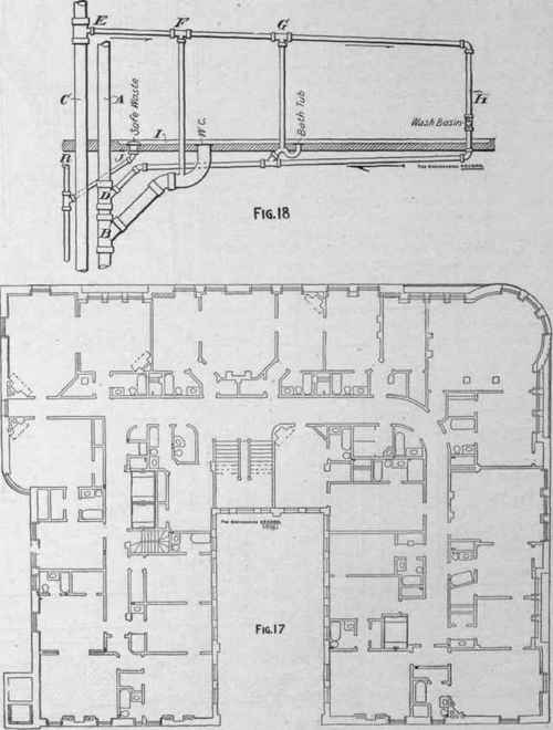
Figure 27 is a plan of one of the guest floors showing the arrangement of the bath and toilet rooms. The position of the vertical hot and cold water risers is indicated by pairs of small black circles. The arrangement of all the other guest floors is substantially similar to that shown. Each hot and cold water riser and circulation pipe has an independent globe valve shut-off. A brass tag fastened to each valve is plainly stamped with a letter designating the particular section the valve controls. Upon the house service side of these valves ½-inch globe valves are connected to the galvanized-iron pipe I, Fig. 3, leading to a sink in the engine-room. Through these valves and pipes the lines may be emptied if necessary. All rising lines are parallel below the eighth floor, and all the pipes in the upper system are extra heavy to sustain the maximum pressure due to a head of 244 feet at the lowest point.
All of the fixtures are set on full-size marble slabs, having a ½-inch countersink for a save-all, with a 3-inch brass rose, screw-top strainer, connected to a 1¼-inch galvanized-iron waste pipe with a good incline and entering its 2-inch sectional save-all waste pipes R, Fig. 18, by a 45-degree connection. All rooms in which plumbing fixtures are located have tiled floors, tile wainscoting 7 feet high, and heavy plate-glass mirrors permanently set into the walls. All stall partitions are of marble. No toilet-rooms are built against outside walls, but to insure to each room a sufficient supply of fresh air six vertical vent shafts 2'6"x5', equipped with exhaust fans at their tops above the roof, were located in different parts of the building, and the water-closets were clustered as near them as possible, and each was connected to it by a ventilating space formed between the main ceiling and an auxiliary one hung 18 inches below it. The foul air thus removed is replaced by fresh air drawn in from the halls through wall openings just above the floor, which are screened with open bronzed fretwork.
The several soil, waste, and venting stacks, water and circulating pipes were run in the vent shafts and ducts wherever it was possible in order to make access easy for repairs or alterations. Beside the kitchen, laundry, and barber-shop fixtures and other fixtures in the cellar, basement, first, sixteenth, and seventeenth floors, the 14 guest floors have 210 bathtubs, 316 washbasins, 243 water-closets, 14 slopsinks, and two urinals. Each fixture has an independent trap which is back-vented and has cleanout holes. All water connections have a separate globe valve shut-off. The wastes are of the stand-pipe pattern and all brasswork is nickel-plated. The marble basin slabs are 1½ inches thick and have 14-inch backs. All fixtnres are exposed, the basin slabs being supported by nickel-plated brass legs and the bathtubs resting 5 inches from the floor on marble footings.
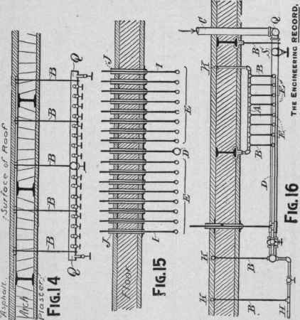
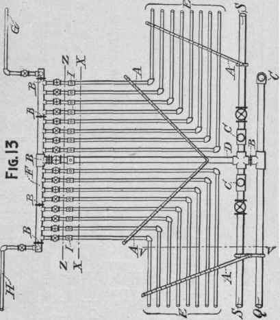
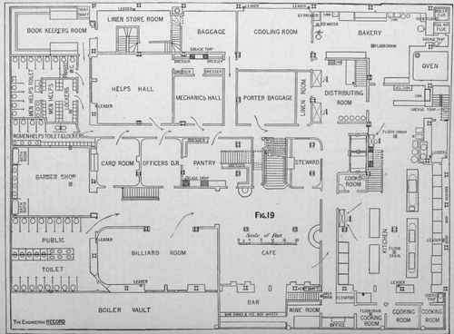
Figure 18 shows the general plan of drainage, trap vent, and safe wastes for the several bath and toilet rooms. A is the 5-inch soil pipe with the 5-inch connection B for the water-closet. From the 5-inch vent stack C at a point well above all fixtures is taken a 2-inch branch E, which has tee branches F and G to the water-closet and bathtub traps and pitches continuously to the branch H. forming the basin waste. This is intended to provide a free circulation of air through all the connected pipes. The safe waste J has a heavy pitch and is accessible for cleaning if obstructed.
Continue to:
My Books

