Plumbing In A New York City Residence
Description
This section is from the book "American Plumbing Practice", by The Engineering Record. Also available from Amazon: Plumbing: A working manual of American plumbing practice.
Plumbing In A New York City Residence
(Published In 1892.)
The residence of Kalmar Hass, Esq., on East Sixty-ninth Street, New York City, is a four-story brownstone-front house, which has just been completed according to plans and specifications of John H. Duncan, architect. Its elaborate plumbing-work, which presents interesting arrangements and detail, was executed by Paul S. Bolger, of New York. The entire second floor of the house is shown in plan in Fig. 1 of the accompanying illustrations, and in vertical section at Z Z, Fig. 1, in Fig. 2. Figures 3 to 6 inclusive show plans at U U, V V, X X, and Y Y, respectively. From these it will be seen that, excepting the boilers and sink in the basement kitchen, there are no plumbing pipes or fixtures whatever in the main building, and, excepting the basement laundry tubs and the butler's sink, all the plumbing is in the special brick-walled tower, which absolutely isolates all the baths and water-closets and the soil and vent pipe risers to which all fixtures are connected.
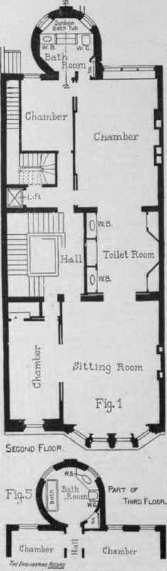
Fig. 2.
In the second and third floor toilet-rooms the washbowls W B, W B, Fig. 1, are entirely unconnected with any plumbing. Stationary oval bowls are set in marble tables, but are fitted only with overflow and waste terminating in a long, vertical ferrule which discharges into a special movable brass nickel-plated sloppail, the bottom of which is cushioned by a rubber-bearing ring sprung over a groove made for it in the flange. The water is supplied by pitchers. All the rising lines, 12 to the second floor and nine to the tank floor, are carried together in the corner S of the tower, where they are run behind a movable panel, which incloses them and leaves them entirely accessible.


A double water-back in the kitchen range is connected with two 100-gallon boilers. One of them is double, providing hot water under street and tank pressure for all purposes except for the second-floor bathroom, which only is supplied by the other boiler under street pressure. Connecting pipes and valves are so arranged that this boiler may easily be put under tank pressure, or its hot water may be turned into the delivery pipe from either of the other boilers, as for an excessive demand by the laundry tubs, or that the double boiler can at pleasure be made to deliver to the second-floor bathroom, the principal consideration being, however, to afford a discharge for the bath boiler if its water is not required for the second-floor bathroom and becomes too hot.

The kitchen boilers are shown in diagram in Fig. 14. A is the double boiler for general house supply, the inside part being under tank and the outside part under street pressure. B is the special bath boiler. Both boilers are heated from the kitchen range C by the circulation pipes D D D D. The cold-water supply comes from the city mains by the pipe E, with branches F F F to supply the boilers and G to supply the basement fixtures and the butler's pantry. The cold supply from the attic tank is by pipe H, filling the boilers through pipes K K. The special hot delivery L connects with the second-floor bathroom and may be put into communication with the street-pressure house boiler through pipe M by opening valve N, which is usually closed. The street-pressure hot-water delivery O connects with all basement and cellar fixtures. Tank pressure hot water is delivered to the upper floors through P, and Q Q are hot-water return-circulation pipes. The sediment pipes R R discharge into a cellar sink. S are the soil and vent risers, etc. shown in shaft S, Figs. 1,4, 5. Ordinarily, valves T T T N and U, which admit tank pressure to the special boiler, are closed and all others are open. Check valves I I are provided, opening up with street pressure against the tank pressure, to prevent the possibility of the escape of tank water into the street mains. The check valve J, which is soldered shut, acts as a stop,between the tank and street pressure hot water, and is placed there to preserve a symmetrical appearance. V V are dummy valves with the wings removed so that it is impossible to close them. They are placed there only for the sake of uniformity of appearance.

Fig. 12.

The second-floor bathroom, shown in enlarged plan in Fig. 7, has a white marble floor, high wall panels and an ornamental domed ceiling. It is attractive for its elegance, spaciousness, and for its unique sunken bath, which is lined with white marble and forms a large pool below the floor level, and is reached by descending marble steps. It is supplied with hot and cold water issuing from a dolphin's head at R, the supply being controlled by valves P P.


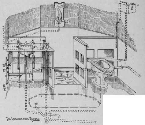
Fig: 10.


The. Engineering Record.
An overflow and waste valve O allows of emptying the bath through strainer N. The movable panel M allows of access to all the risers. Of these A is the soil pipe, B back-air pipe, C D and E respectively-special cold and hot supply and return-circulation pipes from the separate boiler serving this room only. The hot and cold-water supplies and the hot-water return-circulation pipes serving the upper floors are indicated by F G and H. Other reference letters signify: I, the cold-water supply pipe from the tank; J, the pump delivery pipe to the tank; K the sate waste pipe; and T a telltale pipe.
An outline section and elevation at Z Z, Fig, 7, of the sunken bath is given in Fig. 8, showing the deeply countersunk 8-inch marble slab L, lining the bottom of the tub. A perspective from Q, Fig. 7, is given in Fig. 9, showing one end of the tub and its valves P P O, which may be readily operated without leaving the tub. The perspective from point X, Fig. 7. given in Fig. 10 shows the exposed silver-plated piping for the not and cold-water supplies and indicates the arrangement of the waste and vent pipes in the chambers formed by the double flows between the marble tiling and the bottom of the bathtub. The connections to the risers of the branches serving this room are indicated by dotted lines on Fig. 7. E is a connection for a gas stove, and C is the water-closet flush tank entirely concealed behind the marble wainscoting. As it is impracticable to draw water here for household use in pitchers or other portable vessels from the bath or basin cocks, the two self-closing hot and cold-water cocks D D have been set at the side of the washstand for the housemaids' use, and a similar arrangement is provided in the third-floor bathroom.

The sunken bath is surrounded by a special boiler-iron tank, Fig. 11, calked water-tight and supported on four special rolled iron I beams LLLL, Fig. 7, which are built into the tower walls, just above the dome of the smoking-room, and about 3 feet below the wooden joist of the bathroom floor. This tank was carefully calked water-tight and painted; then a thick bed of cement mortar was spread on the bottom, a thick layer of loose fibrous asbestos was pressed down on it before it set, and another thin layer of cement mortar immediately placed on top of the asbestos to receive the marble bottom slab of the bathtub lining. The sides were done in exactly the same manner, and finally the floor marble was laid, covering the edges. The asbestos was designed to prevent radiation of heat, and it was intended to have its fibers cohere thoroughly to the cement.
Figure 12 shows the connection of the waste pipe and strainer N, Fig. 6. The brass waste A, connected to a unique overflow valve O, Figs. 7 and 9, has an extra heavy flange threaded to receive the special sleeve B, which screws down and tightly grips the bottom plate of the tank, making a tight joint by compressing the gasket D and packing E. The sleeve B receives the extra heavy neck of strainer N, which may be removed at will. Figure 13 is a view of the 1,000-gallon house tank on the fourth floor of the tower. It is built of 2-inch boards, and stands in a lead safe. It is filled through the 1¼-inch pipe J and ball cock B, which admits water from the street mains during the night when the pressure is sufficient to rise to this height, but provision has been made to convert J into the delivery pipe for a force pump, if necessary, when the cock B would be removed. A is a 1¼-inch overflow discharging into the fourth-floor slopsink. C is a ¾-inch telltale discharging, together with the safe waste, into the basement sink. D D are relief pipes from the highest points of the hot-water circulation systems, and are provided with a ball cock F, which is set 3 inches higher than B so as always to remain open unless the street pressure in the boiler should cause their water to rise above Z Z, and escaping through D D to fill the tank to nearly the height of telltale C, when it would close until some water was drawn.
Continue to:
My Books

