Description Of Boilers
Description
This section is from the book "A Treatise On Architecture And Building Construction Vol4: Plumbing And Gas-Fitting, Heating And Ventilation, Painting And Decorating, Estimating And Calculating Quantities", by The Colliery Engineer Co. Also available from Amazon: A Treatise On Architecture And Building Construction.
Description Of Boilers
122. Boilers containing tubes are divided into two chief classes. Those which have the hot gases passing through the tubes are called fire-tube boilers, while those which have water upon the inside of the tubes and hot gases upon the outside, are called water-tube boilers.
123. The return-tubular boiler is shown in Figs. 46

Fig. 48.
and 47. It is so called because the hot gases pass along under the shell of the boiler and return through the tubes to the smokebox B; the gases then flow into the smokestack C. The boiler is supported upon the side walls by means of angle brackets A. These should carry the entire weight of the boiler. The tubes can be got at for cleaning by opening a door in front of B, and the soot and ashes can be scraped out through the door E. The boiler is usually provided with a dome D, though this is sometimes left off. Return-tubular boilers are often used for generating steam for heating and power purposes for large buildings.
124. In the locomotive boiler the firebox is internal, and is substantially rectangular in form. The hot gases are conveyed to the smokebox, in a direct course, by the tubes, which are small in diameter and as numerous as possible, so as to secure a large amount of heating surface. The largest part of the total evaporation, however, takes place upon the sides and top of the firebox. These boilers are commonly used for factories, mills, etc.

Fig. 47.
125. Fig. 48 shows a vertical tubular boiler designed for low pressure and small work. The tubes are short, and the firebox is very large in proportion to the size of the shell. The hot gases, after passing through the tubes, are passed downwards over the outer surface of the shell, and are allowed to escape through an outlet Q near the bottom. The jacket S consists of a metal shell, which is lined with non-conducting and refractory material. An inclined partition P extends around the boiler to the point X, and compels the gases to pass over nearly the whole outer surface of the boiler shell. The heating surface is thus considerably increased.

Fig. 48.
126. A water-tube boiler is shown in Fig. 49. It consists mainly of a large number of wrought-iron or steel tubes T, which are inclined at an angle of about 15° to the horizontal. The tubes are connected at each end to manifolds, or headers, H, and seven or eight of these vertical rows of tubes are placed side by side. Each header is connected to the steam drum B by tubes C, C. The water flows towards the front headers and passes up into the steam drum, where the steam bubbles are liberated. The return current flows down through the tubes C into the rear headers. The circulation is very rapid, and the only place where mud or sediment has any chance to lodge is in the mud-drum D. The hot gases are compelled to pass over the tubes cross-ways three times, by means of firebrick partitions S and the suspended wall K.
The feedwater is introduced through the feedpipe E. The steam is collected in the dry pipe F, which terminates in the nozzles M and N, to one of which is attached the main steam pipe, and to the other the safety valve.

Fig. 49.
The pressure gauge, cocks, etc. are attached to the column, which communicates with the interior of the shell by the small pipes u and v, the former of which extends into the dry pipe, the latter into the water.
The method of supporting the boiler is not shown in the figure. The usual method is to hang the boiler from wrought-iron girders resting on vertical iron columns. The brickwork setting is not depended upon as a means of support. This make of boiler, in common with many others of the water-tube type, requires a brickwork setting to confine the furnace gases to their proper field. Boilers of the water-tube type are well adapted to the supply of steam for both power and heat. There is a great variety of water-tube boilers made, but the general principles are about the same in all.
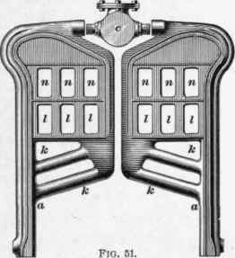
127. A modern type of cast-iron sectional boiler, for low pressure only, is shown in Figs. 50 and 51. There are no direct connections from one section to another, but each one is independently connected, by suitable nipples, to a steam drum c, and to the feedpipes or mud-drums b and d. A pair of sections is shown in detail in Fig. 51.
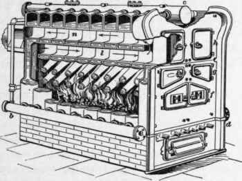
Fig. 50.
The water circulates freely in each section, passing up the inclined tubes k, and descending through the channel in the outer rim of the section. The hot gases impinge upon the tubes k and pass between them to the rear-end section. They then pass forward to the front through the passages, and return to the rear through the upper passages n. An advantageous feature of this construction is the fact that each section is practically an independent boiler, and is provided with good circulation.
Continue to:
My Books

