43. Cantilever Trusses
Description
This section is from the book "Building Construction And Superintendence", by F. E. Kidder. Also available from Amazon: Building Construction And Superintendence.
43. Cantilever Trusses
The term "cantilever" was originally used to designate a projecting beam which served as a bracket; in mechanics it is used to denote a beam or girder fixed at one end, either by being built into a wall, or, most commonly, by extending a sufficient distance beyond its support to form an anchorage for the cantilever. Thus, in Fig. 104, we have a beam resting on two supports; the portion B is a cantilever, while the part C forms the anchorage for it.
[In applying the term cantilever to trusses it is customary to interpret it as including both the projecting arm and the balancing arm, as both portions form one piece of framework, and the term will. be so used in this work.]

Fig. 104.
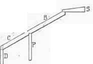
Fig. 105.
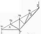
Fig. 106.
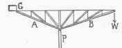
Fig. 107.

Fig. 108.
It is obvious that if the entire beam (Fig. 104) were uniformly loaded the post P would carry the greater part of the weight, and also that an additional load at W might produce an upward pull on the post D, in which case the stress on P would exceed the load on the beam.
Both conditions of loading occur in practice, although it probably most often happens that the outer end of the truss requires anchorage rather than a support.
As applied to roof construction some such arrangement as is shown in Fig. 105 is generally required to make this method of support practicable; that is, a wide centre span, with shorter spans or aisles on each side of it.
The projecting or inner arm of the cantilever is usually made from one-quarter to one-third of the centre span, and a simple truss, represented by S, is used to support the balance of the roof, the centre truss being supported by the arms of the cantilever. In all such cases, therefore, cantilever trusses must be used in pairs, one on each side of the building, and there must be rooms or passages outside of the principal span to permit of the outer or balancing arm. Such an arrangement is generally found in large halls, armories, exhibition buildings, etc., and it might sometimes be provided in other classes of buildings.
Of course, in a large building a simple beam such as is shown in Fig. 105 could not be used, but the principle of construction is the same, whether the cantilever be a simple beam or a large truss.
Pig. 109. - Suggestion for Wooden Cantilever Truss.
Fig. 106 shows the diagram for a truss to take the place of the beam C B, Fig. 105, the single lines representing the tension members and the double lines compression members, and Fig. 109 shows the complete arrangement of the trusses.*
The truss shown in these figures may be extended to almost any extent, and the form of the lower chord may be changed, but the general outline of the truss will be found best adapted for all cases where a wide central roof is to be supported by cantilevers.
For bridge trusses or floors the shape shown in Fig. 107 may be used, and for shed and platform roofs open on one side a truss of the shape shown in Fig. 108 is about the only practicable device. In this latter truss the proportions of the arms are such that a slight support is required at W, thereby bringing the lower portion of the rafter into compression.
*This latter illustration was offered by Mr. John Beverly Robinson as a suggestion for a simple trussed can ileve roof in an article advocating the use of the cantilever in building construction, published in the "Engineering Magazine" for November 1896
It will be seen from Figs. 106-108 that the strains in a cantilever truss are directly the reverse of those in trusses supported at both ends, the upper chord or rafter in the cantilever being in tension, while in all other trusses, except the hinged arch, it is in compression.
44. Advantages And Disadvantages Of The Cantilever Truss
The special advantages possessed by the cantilever truss are: a greater clear height in the centre than can be obtained with any other type (excepting the three-hinged arch), a light and graceful appearance, no horizontal thrust, and consequently no tie-rods required. The particular advantage of this truss for very great spans is that it can be erected without scaffolding under the centre, and in bridge work this is considered as its only advantage.
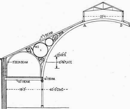
Fig. 110. - Cantilever Truss, Agricultural Hall, Norwich, England.
It is claimed by prominent engineers that the cantilever is not an economical type of truss, and not as desirable for spans of 150 feet or more as the three-hinged arch.
It also does not permit of as readily overcoming expansion and contraction as either the three-hinged arch, the bowstring truss or the quadrangular truss. For certain classes of buildings, however, and especially where the central span does not exceed 150 feet, it can perhaps be used with better architectural effect than is possible with other types, and with about the same economy. For roofing platforms, grand stands, etc., where an outer support is not desired, it is the only type of truss available.
45. Examples Of Cantilever Roof Construction
There are few examples of cantilever roof trusses of constructional importance, although there are many examples of cantilever bridge trusses.
Fig. no shows the proportions and some of the details of the roof trusses of the Agricultural Hall, Norwich, Eng. By using curved ribs for the compression members the truss is given a very light and graceful appearance, and it would appear to contain a minimum amount of material.

Fig. 111. - Cantilever Truss, Mining Building, Chicago, 1893.
The portion of the arch between the points A and B was probably put in to preserve the arch effect, as it could have been dispensed with.
Fig. III shows the proportions of the cantilever trusses used in the Mining Building at the Columbian Exposition; the double lines represent the compression members (with the exception of the arched chord of the outer span, which is in tension) and the single lines the tension members. The cantilever portion of the truss is included between the points F, B, C, D, and the anchorage truss between the points A, F, D. The curved ribs, E, E, E, do not enter the stress diagram, but merely serve as stay braces and in carrying out the arched effect.
In this roof the anchorage arm more than balances the cantilever and its load, and hence exerts a vertical load upon the outer support. The distance between trusses was 64 feet 5 5/16 inches.
Mr. E. C. Shankland, the engineer in charge of the constructional work of the Exposition buildings, says of this truss: "They are interesting as adding another type to the variety of trusses in the park, although they are not at all economical." The truss as built was noticeably heavy.
The lantern truss is a separate quadrangular truss supported by the cantilevers at the points C and P.
Provision for expansion and contraction in this roof was made by means of a 5 1/2-inch slotted hole at the joint P, thus permitting a lateral movement of the 3-inch pin of 2 1/2 inches.
The cantilever trusses have pin-connected joints and the quadrangular truss riveted joints.*

Fig. 112.
Fig. 112 is a diagram of one of the cantilever trusses supporting the roof of the grand stand at the Monmouth Park (N. J.) racing track, the details of which were published in "Architecture and Building" in February, 1890. This is an instance where the cantilever was the only type of truss that could be used, and the form adopted is both simple and economical.
As will be seen from the drawing, the main supporting post extends to the top of the truss, as is usually the case with cantilever trusses, and the truss is riveted to each side of it. The upper and lower chords were made of two angles and a web plate, the upper chords or rafters acting as a tie-beam between the bracing. The bracing consists of angle bars used in pairs and varying from 3 x 2 x \ inches to 3 x 3 x 5/16 inches, the whole frame being connected by rivets.
*The details and stresses in these trusses were published in the "Engineering Record," Vol. XXIX., page 9.
Continue to:
My Books

