IV. Analysis Of Trus5es; "Method Of Joints.". Part 3
Description
This section is from the book "Cyclopedia Of Architecture, Carpentry, And Building", by James C. et al. Also available from Amazon: Cyclopedia Of Architecture, Carpentry And Building.
IV. Analysis Of Trus5es; "Method Of Joints.". Part 3
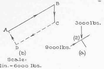
Fig. 18.
of these force polygons is preferable for reasons explained later. Since![]() is in compression, it exerts a push (9,000 pounds) on joint (2) as represented in Fig. 18 (a), and since
is in compression, it exerts a push (9,000 pounds) on joint (2) as represented in Fig. 18 (a), and since![]() is in tension it exerts a pull (7,800 pounds) on joint (3) as represented in Fig. 19 (a).
is in tension it exerts a pull (7,800 pounds) on joint (3) as represented in Fig. 19 (a).
The forces at joint (2) are four in number, the load (3,000 pounds), the force 9,000 pounds, and the force exerted upon it by the members![]() and
and![]() they are represented as far as known in
they are represented as far as known in
Fig. 18 (a). We determine the unknown forces by constructing a closed polygon for all of them. Representing the known forces first, draw AB (1.5 inches long with arrowhead pointing up) to represent the 9,000 pound force and BC (½ inch long with arrowhead pointing down) to represent the load of 3,000 pounds. Next from A and C draw lines parallel to the two unknown forces and mark their intersection D; then the force polygon is ABCDA and the arrowheads on CD and DA must point as shown. CD (1.25 inches = 7,500 pounds) represents the force exerted on joint (2) by![]() since it acts toward the joint the force is a push and member
since it acts toward the joint the force is a push and member![]() is in compression. DA (0.43 inches = 2,580 pounds) represents the force exerted on the joint by member
is in compression. DA (0.43 inches = 2,580 pounds) represents the force exerted on the joint by member![]() since the force acts toward the joint it is a push and the member is in compression. Member 23 therefore exerts a push on joint (3) as shown in Fig. 19 (a).
since the force acts toward the joint it is a push and the member is in compression. Member 23 therefore exerts a push on joint (3) as shown in Fig. 19 (a).
At joint (3) there are four forces, 7,800 pounds, 2,580 pounds, and the forces exerted on the joint by members![]() and
and![]() To determine these, construct the polygon for the four forces. Thus, AB (1.3 inches long with arrowhead pointing to the left) represents the 7,800-pound force and BC (0.43 inches long with arrowheads pointing down) represents the 2,580-pound force. Next draw from A and C two lines parallel to the unknown forces and mark their intersection D; then the force polygon is ABCDA and the arrowhead on CD and DA must point upward and to the right respectively. CD (0.43 inches = 2,580 pounds) represents the force exerted on the joint by member
To determine these, construct the polygon for the four forces. Thus, AB (1.3 inches long with arrowhead pointing to the left) represents the 7,800-pound force and BC (0.43 inches long with arrowheads pointing down) represents the 2,580-pound force. Next draw from A and C two lines parallel to the unknown forces and mark their intersection D; then the force polygon is ABCDA and the arrowhead on CD and DA must point upward and to the right respectively. CD (0.43 inches = 2,580 pounds) represents the force exerted on the joint by member![]() since the force acts away from the joint it is a pull and the member is in tension. DA (0.87 inches = 5,220 pounds) represents the force exerted upon the joint by the member
since the force acts away from the joint it is a pull and the member is in tension. DA (0.87 inches = 5,220 pounds) represents the force exerted upon the joint by the member![]() since the force acts away from the joint, it is a pull and the member is in tension.
since the force acts away from the joint, it is a pull and the member is in tension.
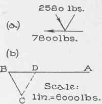
Fig. 19.
We have now determined the amount and kind of stress in members![]()
![]()
![]()
![]()
![]() and
and![]() It is evident that the stress in each of the members on the right-hand side is the same as the stress in the corresponding one on the left-hand side; hence further analysis is unnecessary.
It is evident that the stress in each of the members on the right-hand side is the same as the stress in the corresponding one on the left-hand side; hence further analysis is unnecessary.
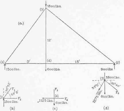
Fig. 20.
2. It is required to analyze the truss represented in Fig. 20(a), the truss being supported at the ends and sustaining two loads, 1,800 and 600 pounds, as shown. (For simplicity we assumed values of the load; the lower one might be a load due to a suspended body. We shall solve algebraically.)
The right and left reactions equal 900 and 1,500 pounds as is shown in Example 1, Page 56. At joint (1) there are three forces, namely, the reaction 1,500 pounds and the forces exerted by members![]() and
and![]() which we will denote by F1 and F2 respect ively. The three forces are represented in Fig. 20 (b) as far as they are known. These three forces being in equilibrium, their horizontal and their vertical components balance. Since there are but two horizontal components and two vertical components it follows that (for balance of the components) F1 must act downward and F2 toward the right. Hence member
which we will denote by F1 and F2 respect ively. The three forces are represented in Fig. 20 (b) as far as they are known. These three forces being in equilibrium, their horizontal and their vertical components balance. Since there are but two horizontal components and two vertical components it follows that (for balance of the components) F1 must act downward and F2 toward the right. Hence member![]() pushes on the joint and is.under compression while member
pushes on the joint and is.under compression while member![]() pulls on the joint and is under tension. From the figure it is plain that the horizontal component of F1 = F1 cos 53° 8' = 0.6 F1*, the horizontal component of F2 = F2, the vertical component of F1 = F1 cos 36° 52' = 0.8 F1, and the vertical component of the reaction = 1,500.
pulls on the joint and is under tension. From the figure it is plain that the horizontal component of F1 = F1 cos 53° 8' = 0.6 F1*, the horizontal component of F2 = F2, the vertical component of F1 = F1 cos 36° 52' = 0.8 F1, and the vertical component of the reaction = 1,500.
Hence 0.6 F1 = F2, and 0.8 F1 = 1,500; or, F1 = 1,500 / 0.8 = 1,875 pounds, and F2 = 0.6 X 1,875 = 1,125 pounds.
Since members![]() and
and![]() are in tension and compression respectively,
are in tension and compression respectively,![]() pulls on joint (4) as shown in Fig. 20 (c) and
pulls on joint (4) as shown in Fig. 20 (c) and![]() pushes on joint (3) as shown in Fig. 20 (d).
pushes on joint (3) as shown in Fig. 20 (d).
The forces acting at joint (4) are the load 600 pounds, the pull 1,125 pounds, and the forces exerted by members![]() and
and![]() the last two we will call F3 and F4 respectively. The four forces being horizontal or vertical, it is plain without computation that for balance F4 must be a pull of 1,125 pounds and F3 one of 600 pounds. Since members
the last two we will call F3 and F4 respectively. The four forces being horizontal or vertical, it is plain without computation that for balance F4 must be a pull of 1,125 pounds and F3 one of 600 pounds. Since members![]() and
and![]() pull on the joint they are both in tension.
pull on the joint they are both in tension.
Continue to:
My Books

