The Size And Capacity Of Drains. Part 3
Description
This section is from the book "The Principles And Practice Of Modern House-Construction", by G. Lister Sutcliffe. Also available from Amazon: How Your House Works: A Visual Guide to Understanding & Maintaining Your Home.
The Size And Capacity Of Drains. Part 3

Flu. 810 -Data for Calculating Flow In Circular Sewers.
C.C = carrying capacity. H. = height in feet; D. - diameter or width at springing in feet; P.c.c. = proportional earning capacity (the width, D, at springing of the arch = 1 in each case); S.A.P. -sectional area of flow in square feet; w.p.=wetted perimeter in feet; h.m.d. = hydraulic mean depth in feet
The efficiency of 4-inch, 6-inch, and 9-inch pipes at the respective gradients of 1 in 40, 60, and 90, and at various depths of flow, is shown in Table XXVI.
Table XXVI. Hydraulic Mean Depth, Velocity, Discharge, Ad, Of 4, 6, And 9-Inch Circular Drains
Proportion of Sectional Area occupied by the flow | Depth in Inches. | Sectional Area of flow in square feet | H.M D in feet | v. In feet per minute. | D. in cubic feet per minute. | |
9-inch pipes falling 1 in 90. | Full | 9 | •442 | 187 | 257.0 | 114 |
3/4 | 6 3/4 | .355 | •225 | 291.1 | 1039 | |
2/3 | 5 2/5 | •309 | •216 | 2834 | 881 | |
1/2 | 4 1/2 | 221 | •187 | 257 0 | 57 | |
1/3 | 3 3/5 | 127 | 138 | 2100 | 26 8 | |
1/4 | 2 1/4 | •086 | 109 | 179.9 | 15.6 | |
6 inch pipes tailing 1 in | Full | 6 | 19634 | •125 | 240 | 471 |
3/4 | 4 1/2 | •158 | •1508 | 272 | 424 | |
2/3 | 3 5/4 | 139 | 14f>6 | 265 | 354 | |
1 | 3 | •09817 | .125 | 240 | 235 | |
1/5 | •0573 | 0931 | 196 | 11.0 | ||
1/4 | 1 1/2 | •0384 | •0733 | 168 | 64 | |
4 inch pipes tailing 1 in 40. | Full | 4 | •0873 | 0835 | 224 | 196 |
3 | •0762 | 1006 | 254 | 178 | ||
2/3 | 2 2/5 | 0618 | •0970 | 247 | 151 | |
i | 2 | •0436 | •0835 | 224 | 9.8 | |
I | 1 3/5 | 0255 | •0621 | 183 | 4 6 | |
1/4 | 1 | •017 | •0489 | 157 | 2.7 |
For other sizes of circular drains, the calculations will be simplified by the use of the following table: -
Table XXVII.1 Data For Calculating Flow In Circular Drains
Depth of Flow | Area. | Wetted Perimeter | H.M.D. |
Full | •7854 d2 | 3.1416d | .25d |
| | •632 d2 | 2.095 d | .296d |
•556 d2 | 1.911d | •292 d | |
1/2 | •393d2 | 1.571d | •25 d |
1/3 | .229 d2 | 1.231d | •186d |
1/4 | .154d2 | 1.047d | .147d |
1 This table is taken from The Sewerage Engineer'sNote-Book,by Albert Wollheim, Assoc.M.Inst.C.E.
When it is required to ascertain the discharge of a pipe at any specific depth of flow, the following formula may be used: -
A - Sectional area of flow. P = Wetted perimeter. HMD= Hydraulic mean depth.
r- radius. d - diameter. = ratio between diameter and circumference, or 1:3 1410.
HMD =A/P
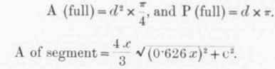
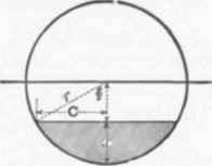
Fig. 311. - Diagram to ILLUSTRATE Trig, onometrical Calculations of the Dis-charge frum a Circular Drain.
(.Semi-chord c may be found by right-angled trigonometry).
Perimeter of segment = number of degrees x .017453 radius.
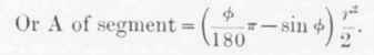
Those not accustomed to the use of trigonometry may find the following method of solution of the problems somewhat simpler: -
KT = radius of circle. N O T = chord of whole arc. N Q = chord of half arc. O Q = versed sine (or depth of flow). N TQ = segment.
From NK2 subtract OK2, and the square root of the remainder = ON = 1/2NT.
N Q may he found from the following, - N Q =√ON2+ OQ2. Wetted Perimeter NQ T = (8 NQ-NT)/ 3.
Area of Segment N TQ = 2/3 (N T x O Q) +OQ3/2NT
Fig 312. - Diagram to Illustrate Arith. metical Calculation of the Discharge from a Circular Drain.
Continue to:
My Books

