Chapter XI. Graphical Analysis Of Strains In Trusses
Description
This section is from the book "Safe Building", by Louis De Coppet Berg. Also available from Amazon: Code Check: An Illustrated Guide to Building a Safe House.
Chapter XI. Graphical Analysis Of Strains In Trusses
HE same general rules which apply to beams and girders apply T equally well to trusses ; but as the latter are made up of a large number of parts, some sustaining the loads directly, others transmitting the consequent strains and thus helping indirectly to sustain the loads, it becomes difficult and often very complex to follow out all the strains arithmetically. For this reason the graphical method is generally used, and for the architect, who has many other things to remember, besides strains and stresses, will always be found to be the most convenient.
There are three steps necessary in designing a truss :
1st. Ascertaining the amounts of loads on each part, and their points of application
2d. Ascertaining the consequent strains on each member of truss.
3d. Designing the members and joints of truss.
In calculating trusses it is always assumed that all the members meeting at any joint are connected by a single pin, and are, therefore, at liberty to move around this pin, until they assume equilibrium towards each other, when of coarse, they will all counterbalance each other and remain stationary. All loads are, therefore, assumed to act directly on the joints, and are considered as vertical forces at these points (except where wind is allowed for separately). It will frequently happen, however, that the loads are not placed directly over the joints.
For instance, the load might be uniformly distributed over the entire rafter (or chord) : in that case, we should have to assume one-half the load on each panel as coming directly (and vertically) on the joint (that is, each joint would act as a vertical reaction, made up of several parts), and afterwards when designing the truss members, we should have to add sufficient material to the rafter (or chord) to take care of the transverse strain, due to the uniform load.
Transverse strain on members.
Or, again, we might have a load w, as shown in Figure 212. The amounts of this load coming on joints Nos. 2 and 3 would be Figured exactly the same as reactions (Formulæ 14 and 15).
In these formulæ p would be load No. 2 ; q load No. 3 ; l would be the length of rafter from No. 2 to No. 3 ; m would be the length of C or from No. 2 to load ; and n would be the length of D or from load to No. 3.
All these lengths can be measured either along the rafter, or horizontally between the vertical lines, the result will be the same.
Where loads are suspended from the lower chord, or what amounts to the same thing - rest on same (as ceilings for instance), the load can be considered as hanging from the bottom chord as shown at w111 Figure 212.
Joints act as reactions.
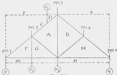
Fig.212.
This, however, seriously complicates the strain diagram, it is better therefore to consider (which is also the fact) that the load w111 is transferred directly to No. 3 by the tie-rod A B. We will therefore in making our strain diagram add the amount of w111 to load No. 3, and must remember later to add an amount of tension (equal to w111) to rod AB over and above that found by strain diagram. If we had a load w11 placed half-way between p and w111 we should have to make the tie-beam or lower chord sufficiently strong to bear this transverse load in addition to the tension existing in it. In this case, the point w111 andp would be the reactions for load w11 and the rod A B would transfer its share up to No. 3 in addition to load w111 But as a rule it is more economical to transfer the load w11 up to joint No. 2 directly, by means of the tie-rod. When making the strain diagram, however, this rod should be omitted and the truss shown as at H. Otherwise it will be found that the corresponding points f and g of strain diagram would coincide. This would mean that there was no strain on F G due to the strains in truss ; and this is a fact, as the only stress in the rod is in resisting the direct tension due to the load hanging from No. 2 by the rod.
Loads on lower Chord.
When Figuring the reactions p and q they should be Figured by the Formulas (14) to (17) inclusive. If all the loads are uniformly or symmetrically placed along the truss, each reaction will be just one-half of the total load. If not, then the truss is considered the same as if it were a beam and the reactions Figured by the formulas, the distances m, n, r and s are measured horizontally between verticals as shown; the distance l is, of course, the entire (horizontal) distance from p to q. Wind can safely, as a rule, be assumed to act vertically on the truss and to simply add just so much to the calculated dead load. The writer generally adds for this climate (New York City) 30 pounds per square foot of surface of roof (measured on the slant, not horizontally). This will do for small roofs and approximate calculations of large roofs. This allowance will include the necessary allowance for snow, for, if the roof is steep, the snow will either slide off, or be blown off, and if the roof is flat the wind pressure will be very much smaller and the reduction in wind pressure will fully offset the weight of snow.
Of course taking the wind as a vertical dead load involves two errors: first, the wind is never on the entire roof, as it can manifestly act on one side only; secondly, the wind does not act vertically. Where wind pressure is calculated separately it is assumed to act at right angles to the surface of the roof and on one side only. In large trusses this should always be done, as it will frequently be found that stresses in certain members will be reversed.
That is, members, which under a dead, vertical load show only tension or compression in the strain diagram may (with wind taken normal to roof and on one side only) be reversed and show, respectively, compression or tension.
Reactions at Ends.
Allowance for Wind and Snow.
General Rule.
Separate Diagram for Wind.
Reversal of Strains.
Iron trusses, over eighty feet long, need some arrangement to allow for expansion and contraction. In roof trusses this is provided by anchoring down one end and leaving the other end free to move (horizontally) by placing it on rollers.
It will readily be seen that where there are rollers the effect on the truss will be very different, according to which side the wind is blowing from. In such trusses, therefore, it will be necessary to make three strain diagrams, one for vertical dead load (including snow but no wind); one for wind only on right side; one for wind only on left side.
The truss must then be designed to withstand the strains due to the dead load only; and enough added, where necessary, to withstand the additional or different strains due to either pressure. Where both strains are of the same nature they should be added together; where they are of opposite natures they will, of course, offset each other, but the member should be strong enough or stiff enough to withstand either separately.
As the wind acts horizontally, it will on striking a roof of course cause a different pressure at right angles to the inclination of roof, than is its pressure against a vertical surface. This pressure will therefore vary with the inclination of the roof. To determine it, it is assumed that the greatest wind pressure per square foot of roof surface will never exceed forty pounds. For steep roofs with an inclination of 60° to 90° with the horizon, this is the pressure assumed.
For roofs forming smaller angles with the horizon a complicated trigonometrical formula is used. Its results are as follows:
Wind Pressure Dependson Inclination.
Continue to:
My Books

