The Ice Boat
Description
This section is from the book "The Scientific American Boy", by A. Russell Bond. Also available from Amazon: The Scientific American Boy.
The Ice Boat
School commenced on the 20th of September that year, so we hadn't much time to spare. Work was begun immediately on the ice boat. Our first ice boat was rather a crude one. A 2 by 4 inch scantling 14 feet long was used for the backbone of the boat. The scantling was placed on edge, and to lighten it and improve its appearance it was tapered fore and aft from a point 4 feet from the bow end. The thickness of the ends of the backbone was but 2 inches, as shown in Fig. 163. To the under edge of the backbone, 5 feet from the forward end, a crosspiece was nailed. This crosspiece was a 1-inch board 6 inches wide and 9 feet long. Braces were then run from the ends of the crosspiece to the forward and rear ends of the backbone, and at the rear end several boards nailed across the braces served as a seat for the boat.
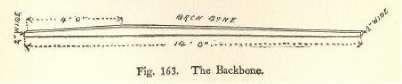
Fig. 163. The Backbone.

Fig. 164. Frame of the Ice Boat.
Our next task was to rig up the runners. For these we used skates, which were so arranged that we could remove them whenever we wanted to. Three blocks of wood were used for the runner shoes. Two of them were cut from a 2 by 4 scantling and measured a foot in length. The third block was only 1 inch thick, but was otherwise of the same dimensions. The skates were laid face downward on the blocks with the clamping levers open; then we marked the places where the clamping jaws touched the wood and drilled holes at these points. The forward end of each block was also tapered off to fit flat against the face of the skate. Then by inserting the jaws in the holes and closing the levers, the skate was clamped to the block, just as it would be to a shoe. The two 2-inch blocks were bolted to the ends of the crosspiece, but the third block needed further attention, as it was to be used for the rudder or steering runner.

Fig. 165. Runner Shoe. Fig. 166. The Rudder Shoe.
The rudder post was shaped from a block of hardwood 3 inches square and 10 inches long. Two inches from the lower end saw cuts were made in the side of the block to a depth of 3/4 inch. Then with a chisel the sides were split off, forming a large pin with a square shank 8 inches long. Next the corners of the shank were cut off, rounding it to a diameter of 1-1/2 inches. The runner block was fastened securely to the head of the rudder post with screws. A 1-1/2-inch hole was now drilled into the backbone at the stern end to receive the rudder post. A tiller was next cut out of a 1-inch board to the shape shown in Fig. 167. A slot was cut in the end of the tiller, and the latter fitted snugly over the top of the post, where it was held in place by screws threaded in through the sides.
The mast of our boat was a pole 8 feet long, tapering from a diameter 2 inches at the base to 1-1/2 inches at the top. A step for the mast was cut from a 2 by 4 block 8 inches long. A 2-inch hole was drilled into the face of this block. We had no drill large enough to bore this hole, but accomplished the same result by drilling eight 1/2-inch holes inside of a 2-inch circle
(Fig. 168), and then used a chisel to cut off the projecting pieces. The mast step was firmly bolted to the backbone at its thickest part, that is, just four feet from the forward end. The mast was braced with stay ropes stretched from the top to the forward end of the backbone and to the ends of the crosspiece. A 9-foot pole, tapering from 1-1/2 inches to 1 inch in diameter, was used for the boom of the mainsail, and for the gaff we used a 6-foot pole of the same diameter.
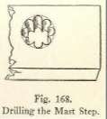
Fig. 167. The Tiller.
Fig. 168. Drilling the Mast Step.
The dimensions of the mainsail are given in Fig. 169. For mast hoops we used curtain rings. Five were attached to the sail along the luff, and one was fastened with a piece of leather to the end of the gaff. We used a different scheme for holding the boom to the mast. The forward end of the boom was flattened at the sides and a couple of cheek blocks were bolted on, forming jaws of the shape indicated in Fig. 170. The jaws were whittled out to fit nicely around the mast, and were kept from slipping off by a piece of rope passed around the mast and threaded through the ends of the cheek blocks. Half a dozen small pulley blocks were now procured, of the type used on awnings. A rope called the throat halyard was strung from the throat or forward end of the gaff through a pulley block near the top of the mast, and led down to the backbone, where it was "belayed," or wrapped around a cleat. The cleat, which was whittled out of a stick of wood, was made in the form indicated in Fig. 171. A short length of rope was strung through a pulley block and tied with some slack to the upper end and to the center of the gaff. This rope is called a "bridle," and to the pulley block on this "bridle" a rope was attached called the "peak halyard." The peak halyard was passed through a pulley block at the top of the mast, and belayed on a cleat at the side of the backbone. For the main sheet (that is, the rope used for guiding the mainsail) two pulley blocks were fastened to the backbone, one just in front of the seat and the other a few feet further forward, and two more were lashed to the boom, midway between these blocks. The sheet was fastened near the aft end of the backbone and then strung through the blocks in the order illustrated, the free end of the sheet being brought back to the seat, where a cleat was provided, to which it could be secured when desired.
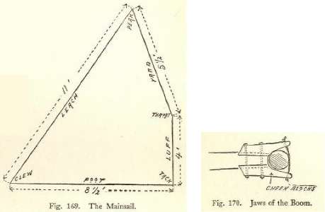
Fig. 169. The Mainsail. Fig. 170. Jaws of the Boom.
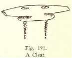
Fig. 171. A Cleat.
The jib-sail was now cut out to the dimensions given in Fig. 172. The foot of the sail was lashed to a jib-boom 3 feet 4 inches long. The jib-boom was attached to the backbone at its fore end by means of a couple of screw eyes. The eye of one of these was pried open, linked through the other and then closed again. One of the screw eyes was now screwed into the head of the jib-boom and the other was threaded into the end of the backbone. The upper corner or "head" of the jib was tied to a jib-halyard, which passed through a block at the top of the mast, and was secured on a cleat on the backbone. On the jib we used two sheets. They were attached to the end of the jib-boom and passed on opposite sides of the mast through blocks on the crosspiece to the stern of the boat, where separate cleats were provided for them.
This completed our ice boat, and a very pretty little boat she was. It was with great reluctance that we furled the sails, unstepped the mast, and stowed away the parts in our attic until old Jack Frost should wake up and furnish us with a field of smooth ice.

Fig. 172. The Jib-sail.
Fig. 173. The Ice Boat Completed.
Continue to:
My Books

