Cylindrical Cams. Development Of Cylinder Cams
Description
This section is from the book "Modern Shop Practice", by Howard Monroe Raymond. Also available from Amazon: Modern Shop Practice.
Cylindrical Cams. Development Of Cylinder Cams
Suppose that the outline of the translation cam as developed in Fig. 91 be wrapped around a cylinder whose circumference is exactly equal to Dx, and that the lines represent a spiral groove cut into the surface of the cylinder. If, then, a follower roll be allowed to remain in this groove while the cylinder is rotated on its axis, the cycle of follower movement will be . repeated as long as we choose to rotate the cylinder. Such a grooved cylinder is known as a cylindrical cam.
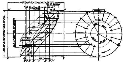
Fig. 02. Development of Cylindrical Cam.
Fig. 92 shows a cylindrical cam in two projections. Attention is called to the tapering follower roll used. This is because it is necessary that points on the sides of the groove and the surface of the roll have the same velocity about the center C. The roll, therefore, must be the frustum of a cone whose apex is at C.
The top of this groove is produced by wrapping Fig. 91 around the surface of the cylinder as previously described. The bottom of the groove is produced by making a translation cam whose base line is equal in length to the circumference of the cylinder at the bottom of the groove, and then wrapping it around that cylinder. This base line for this smaller cylinder is divided into the same number of parts as the line Dx, the divisions, however, all being proportionally smaller. The length of the follower path, and its divisions, are in nowise different from those shown in Fig. 91; and the method of developing the outline of the cam is precisely the same.
The wrapping of these translation cams, for purposes of the drawing, is accomplished by means of dividers and compasses, according to the principles for the development of cylinders, as explained in Mechanical Drawing, Part III.
The limitations of construction of cylindrical cams are considerably greater than those of the simpler rotating cams; and it is more frequently a question of experiment and trial to get the proper surfaces, than it is of exact theoretical layout on the drawing board.
Continue to:
My Books

