Construction Of A Pile-Driving Engine
Description
This section is from the book "Cassell's Cyclopaedia Of Mechanics", by Paul N. Hasluck. Also available from Amazon: Cassell's Cyclopaedia Of Mechanics.
Construction Of A Pile-Driving Engine
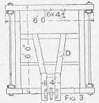
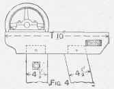
The accompanying illustrations show a pile-driving engine suitable for driving piles lift, by 6in. by 2 in., with a, ram of about 1 1/2 cwt., to be raised by manual power. The base frame shown in Fig. 3 is composed of four 6-in. by 4 1/2-in. red (1 sal sills, stub-mortised and tenoned together, and secured by two 3/4-in. bolts that can be made to do duty for axles for the wheels, if wheels are used. The two guides for the ram are 4 1/2in. by 4 1/2in.,and are tenoned and pinned into the head and sill frames; the girders are kept parallel by a 3/4-m. bolt just below the head. The front raking braces B are of 44-in. by 4 1/2-in. stuff, and are bridle-notched to the guides, and secured with 1/2-in. coach screws. The back braces D (4 in. by 4 in.) are tenoned and pinned into an intermediate sill, framed between the main sills about 4 ft. back, and when a platform is used an additional joist is framed in as shown to stiffen the floor (this floor is omitted in the illustration). The head frame is constructed as shown in Fig. 4; a 4-iu. by 3-in. rail is framed in at the rear end, and collars are welded on the bolt E to keep the distance parallel. The gin or pulley runs in a casting bolted to the top of the frame. The ram, if made of greenheart of the given dimensions, will weigh 1 1/2cwt.; but if made of Jarrah another 9 in. in length will be required; the lower end of the ram is bound with a wrought-iron flange 1 in. by 1/2 in. The trip, or monkey hook, shown in the illustration is one of the best of its kind: several 1/2-in. boles are bored in the guides before framing them in, and a 4-in. iron bar is placed at any height from which it is desired to drop the ram. As soon as the arm of the monkey reaches the bar, it is tripped out of the eye of the ram, which immediately falls; the counterweight on the front of the hook tilts it down again ready for entering the eye when it is lowered. F is a slider attached to the ram to prevent it jumping away from the guides. If there is much work to be done with the engine it will be advisable to bolt 3/8-in. byl 1/2-in. iron bars on the face of the guides to prevent wear.
Pigs. 1, 2,3 are reproduced to scale of 1 1/4 in. to 1 ft.: Fig. 4 is to a scale of 2 in. to 1ft. Another design for a pile-driver is given on p. 165.
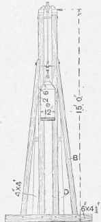
Fig. I.
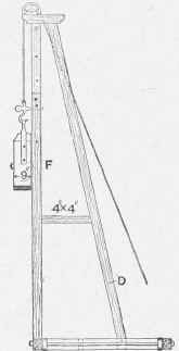
Fig. 2.
Construction of a Pile driving Engine.
Continue to:
My Books

