Press For Mangle Shafts
Description
This section is from the book "Cassell's Cyclopaedia Of Mechanics", by Paul N. Hasluck. Also available from Amazon: Cassell's Cyclopaedia Of Mechanics.
Press For Mangle Shafts
The accompanying drawings show, with scale, a machine for pressing shifts in mangle rollers to be driven by steam. Two belts, one open and the other crossed, drive the pulleys F, L, F, and L, and by means of the striking gears P and Q the pinion A can he made to revolve in either direction, or the straps can be moved to the loose pulleys. As will he seen, the pinion drives the tooth wheel B, and the latter, being keyed on the same shaft as the pinion C, the tooth wheel I) is driven in either direction as required. D has a thread cut in its boss and works the screw E, causing it to move backwards or forwards through the thrust block X. The plain parts of the screw shaft at F and G are for the purpose of preventing accident in the event of the striking gear not being moved quickly enough. Thus, when the tooth wheel D gets on the plain parts it will simply revolve without causing any movement of the screw; then the screw can be turned into the thread of D by the hand wheel H. It will only be at such times as these that the screw shaft will revolve, as the hand wheel H will be locked to the driving head K as indicated.
The driving head K works between the planed sides M and N. The fixed head at 0 is simply for holding the mangle shaft S in position and for adjusting the mangle roller Z; this latter is held in position by means of the four cramps 1,2, 3, and 4 as shown. The backthrust block R, with its slides T, T, can be moved backwards or forwards by means of the hand wheel W and screw working through the block V, and when adjusted can be firmly held to the bed by the two bolts and nuts shown at 5 and 6. The bed should be bolted to iron supports or other suitable foundation by bolts and nuts shown at 7, 8, 9,10,11, and 12.
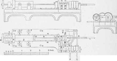
Press for Mangle Shafts.
Continue to:
My Books

